Hardware Reference
In-Depth Information
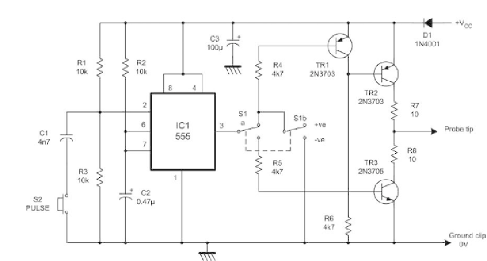
Figure 13.23
Logic pulser circuit
a line up to
+
5Vviaa1k
resistor or by temporarily tying a line to 0 V.
However, on other occasions, it may be necessary to simulate a pulse rather
than a permanent logic state and this can be achieved by means of a logic pulser.
A logic pulser provides a means of momentarily forcing a logic level transi-
tion into a circuit regardless of its current state and thus overcomes the need to
disconnect or de-soldering any of the devices. The polarity of the pulse (pro-
duced at the touch of a button) is adjusted so that the node under investigation
is momentarily forced into the opposite logical state. During the period before
the button is depressed and for the period after the pulse has been completed,
the probe tip adopts a tri-state (high impedance) condition. Hence the probe
does not permanently affect the logical state of the point in question.
Logic pulsers derive their power supply from the circuit under test in the same
manner as logic probes. Here again, the leads of an electrolytic decoupling
capacitor or the
+
5 V and GND terminals fitted to an expansion card make
suitable connecting points.
A typical logic pulser circuit is shown in Figure 13.23. The circuit comprises
a 555 monostable pulse generator triggered from a push-button. The output of
the pulse generator is fed to a complementary transistor arrangement in order
to make it fully TTL-compatible. As with the logic pulser, this circuit derives
its power from the circuit under test (usually
+
5 V).
Figure 13.24 shows an example of the combined use of a logic pulser and a
logic pulser for testing a simple J-K bistable. The logic probe is used to check
the initial state of the Q and /Q outputs of the bistable (see Figure 13.24(a) and
(b)). Note that the Q and /Q outputs should be complementary. Next, the logic
pulser is applied to the clock (CK) input of the bistable (Figure 13.24(c)) and
the Q output is checked using the logic probe. The application of a pulse (using
the trigger button) should cause the Q output of the bistable to change state (see
Figure 13.24(d)).