Hardware Reference
In-Depth Information
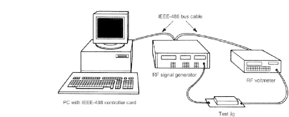
Figure 12.5
Crystal filter test hardware configuration
Hardware
This application is ideally suited to an IEEE-488-based system (based on test
instruments fitted with the requisite IEEE-488 interface which are already
available in the company's test department). Apart from the PC controller (which
will require an IEEE-488/GPIB interface card) the two instruments required are:
•
an RF voltmeter (Marconi 2610 with GPIB interface);
•
an RF signal generator (Marconi 2018A with GPIB module).
The RF signal generator will be configured as a 'listener' whilst the RF voltmeter
will be a 'talker'. A test jig will have to be constructed to accommodate the
filter under test. Furthermore, since the filter source and load impedances are
critical, appropriate matching components must be incorporated into the test
jig. The simplified block schematic of the hardware is shown in Figure 12.5.
Software
The control software is again easily written in QuickBASIC (or equivalent) and
the required program can be based on the following algorithm (expressed in a
form of structured English):
INITIALISE SYSTEM
DISPLAY WELCOME SCREEN
DO
GET SYSTEM PARAMETERS
CONFIGURE IEEE-488 SYSTEM
ENTER FILTER REFERENCE
DO
READ-VOLTAGE LEVEL
INCREMENT GENERATOR FREQUENCY
LOOP UNTIL FINAL FREQUENCY
CALCULATE FILTER SPEC
DISPLAY FILTER SPEC
STORE FILTER SPEC