Hardware Reference
In-Depth Information
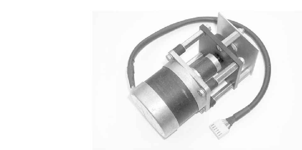
Photo 9.12
Stepper motor
Driving stepper motors
The complex task of interfacing a stepper motor to a PC-based system can be
greatly simplified by using a dedicated stepper motor driver card. Alternatively,
in many light-duty applications, a simple interface can be constructed based
on a specialized stepper motor driver chip (such as the UCN5804). This device
includes all necessary logic to drive a stepper motor as well as output drivers
for each of the four phases. The chip can provide drive for a four-phase unipolar
stepper motor with continuous rating of up to 1.25 A per phase (1.5 A startup)
and 35 V. The inputs are compatible with standard PMOS, NMOS, and CMOS
circuits (note that TTL or LS-TTL may require the use of pull-up resistors in
order to ensure a proper logic 1 input high state).
Figure 9.42 shows a typical stepper motor interface based on the UCN5804.
The stepper motor interface requires three port output lines that operate on the
following basis:
•
The STEP input is pulsed low to produce a single step rotation.
•
The DIRECTION input determines the sense of rotation. A low on the
DIRECTION input selects clockwise rotation. Conversely, a high on the
DIRECTION input selects anticlockwise rotation.
•
The /ENABLE input must be taken low to operate the motor.
The software routines for driving the stepper motor are quite straightforward
and can be simply based on sequences of OUT (or equivalent) instructions
which may be contained within loops where continuous rotation in a clock-
wise or anticlockwise direction is required. For further details (including the
UCN5804's half-step mode) readers should refer to the relevant data sheets.