Hardware Reference
In-Depth Information
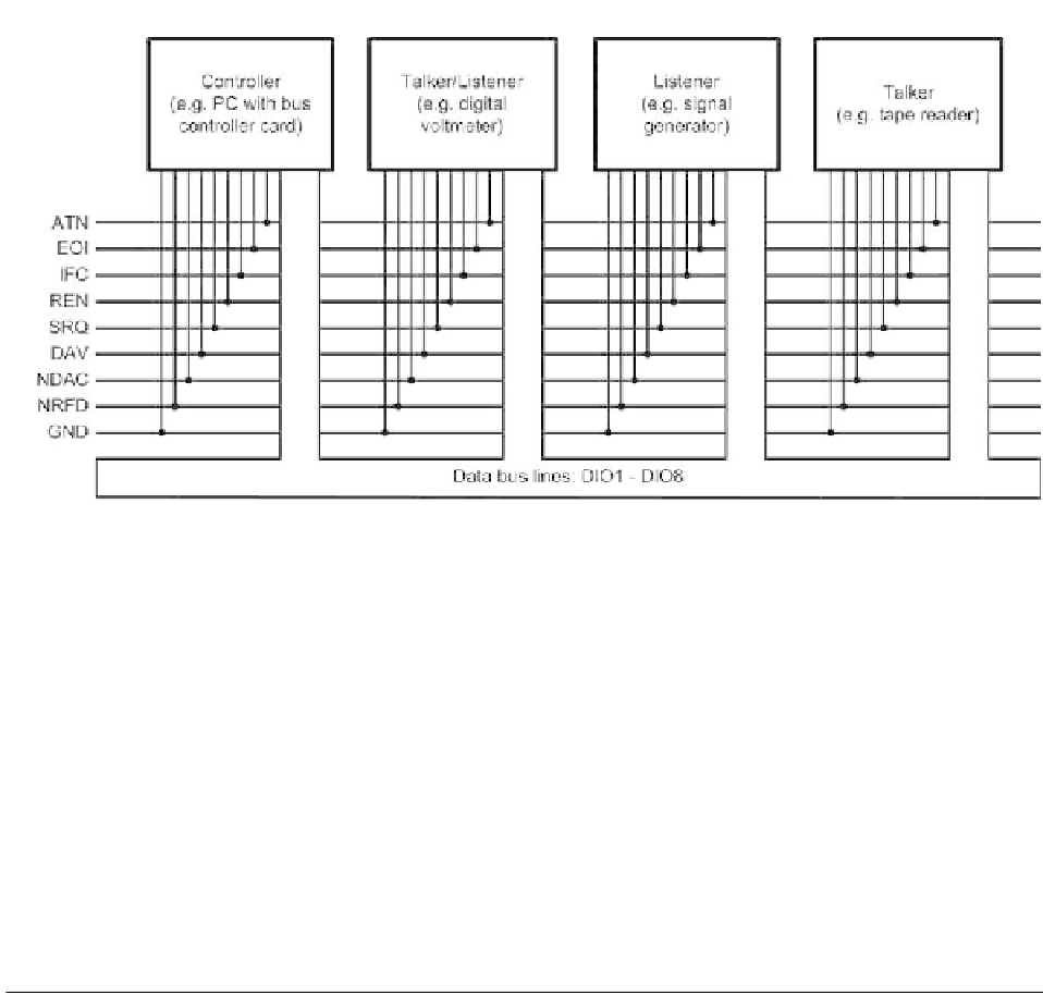
Figure 8.2
IEEE-488 bus showing signals and devices
invariably a microcomputer and, whilst some manufacturers provide dedicated
microprocessor-based IEEE-488 controllers, this function is often provided by
means of a PC or PC-compatible microcomputer.
IEEE-488 bus signals
The IEEE-488 bus uses eight multi-purpose bi-directional parallel data lines
(see Figure 8.2). These are used to transfer data, addresses, commands and
status bytes. In addition, five bus managements and three handshake lines are
provided.
The connector used for the IEEE-488 bus is invariably a 24-pin type (as
shown in Figure 8.3) having the following pin assignment:
Pin number
Abbreviation
Function
1
DIO1
Data line 1
2
DIO2
Data line 2
3
DIO3
Data line 3
4
DIO4
Data line 4
5
EOI
End or identify. This signal is generated by a talker to indicate the last byte of data
in a multi-byte data transfer. EOI is also issued by the active controller to perform
a parallel poll by simultaneously asserting EOI and ATN.
6
DAV
Data valid. Thus signal is asserted by a talker to indicate that valid data has been
placed on the bus.
7
NRFD
Not ready for data. This signal is asserted by a listener to indicate that it is not
yet ready to accept data.
(
continued
)