Hardware Reference
In-Depth Information
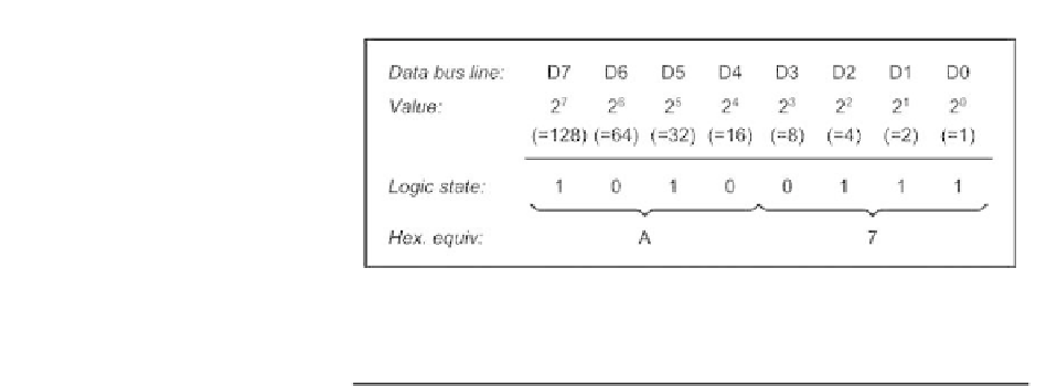
Figure 1.2
Data representation in a microcomputer system
Table 1.2
Relationship between data bus size and largest data value
Number of data lines
Number of bytes
Largest data value
8
1
255
16
2
65 535
32
4
4 294 967 295
Approximately 1.84
10
19
64
8
Table 1.3
Relationship between address bus lines and
linear addressable memory
Number of address lines
Linear addressable memory
16
64 KB
20
1 MB
22
4 MB
24
16 MB
32
4 GB
early PC, XT, and AT models (labelled A0 to A19) and as many as 32 bits in
modern equipment (where the address lines are labelled A0 to A31).
The relationship between data bus lines and the largest data value possible
that can be conveyed
at any particular instant
is shown in Table 1.2.
Similarly, with more address lines it is possible to address a larger memory.
The relationship between address bus lines and
linear addressable
memory is
shown in Table 1.3.
Bus expansion
The system shown in Figure 1.1 can be expanded by making the three bus
systems accessible to a number of expansion modules, as shown in Figure 1.3.
These modules (which invariably take the form of plug-in printed circuit cards)
provide additional functionality associated with input/output (I/O), graphics, or
disk control. Expansion cards are often referred to as 'option cards' or 'adapter
cards', and they provide a means of extending a basic microcomputer system
for a particular application.