Information Technology Reference
In-Depth Information
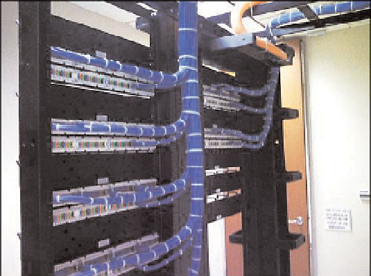
Figure 4-7
Data Center Cabling the Right Way
For example, using under-floor c abling techniques, espec ially w ith a high number of
power and data cables can restrict proper airflow. Another disadvantage with this ap-
proach is that cable changes require you to lift floor tiles, which changes the airflow and
creates cooling inefficiencies.
One solution is a cable management system above the rack for server connectivity. Cables
should be located in the front or rear of the rack to simplify cable connections. In most
service provider environments, cabling is located in the front of the rack.
To d a y 's e n t e r p r i s e d a t a c e n t e r d e s i g n fo l l o w s t h e C i s c o m u l t i l a y e r a r c h i t e c t u r e , w h i c h i n -
cludes DC core, DC aggregation, and DC access layers. This multitier model is the most
common model used in the enterprise and it supports blade servers, single rack unit (1RU)
servers, and mainframes.
Figure 4-8 provides a high-level overview of an enterprise data center infrastructure.
At the edge of the data center infrastructure is the access layer. The data center access
layer needs to provide physical port density and both Layer 2 and Layer 3 services for
flexible server connectivity options.
The data center aggregation layer ties the DC core and DC access layers together, which
provides hierarchy for security and server farm services. Security services such as access
control lists (ACL), firewalls, and intrusion prevention systems (IPS) should be imple-
mented in the data center aggregation layer. In addition, server farm services such as con-
tent switching, caching, and Secure Sockets Layer (SSL) offloading should be deployed in
the data center aggregation. Both the data center aggregation and core layers are com-
monly implemented in pairs for redundancy, to avoid single points of failure.