Java Reference
In-Depth Information
•
Component diagrams. They zoom into the system, describing the various
components
it
is made up of and their
interactions
. In Java components, JAR files are often physically
deployed on the client machine (but not necessarily present locally), and dependencies
could range from compilation and compatibility relationships (for example: “JAR file 'A'
version 2.1 cannot work with JAR files 'B' older than 1.0”) or communication relation-
ships.
These diagrams are used to document the final deployed software system, and are intended
mainly for system management on the client machines and maintenance developers reading.
An often-overlooked aspect of such diagrams is their utility as a design tool for clarifying the
overall deployment mechanisms in a design phase. Unfortunately, such diagrams (when written
at all) are used for documenting the implemented scenario when everything is laid out defini-
tively (mistakes included) after the development phase has finished.
Often the two diagrams are mixed together to provide a more intuitive view of the deployed
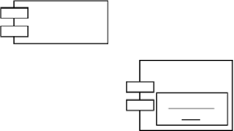
system. Figure A.2 shows the graphical notations for the main entities (component, node,
objects, and their relationships) used in these diagrams.
A Node
A Component
Another Component
communication
:A Contained
Object
F
IGURE
A.2
The main pieces of deployment and component UML diagrams.
We conclude this section with an example of a little system documented with such diagrams,
reported in Figure A.3. The proposed system is a JNLP-deployed application composed of two
JAR files (
core.jar
and
extra.jar
) installed in the JNLP Client cache. The JNLP Client com-
municates with a deployment servlet, located on a remote host called the Deployment Server.
The application communicates with another remote host, called the Business Server, via a
JDBC connection, in order to provide business transactions on a remote database.