Database Reference
In-Depth Information
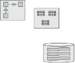
Requirements
Design
Implementation
Semantic
Data Model
Relational
Data Model
Physical
Data Model
Figure 12-1
Physical design in the overall design process.
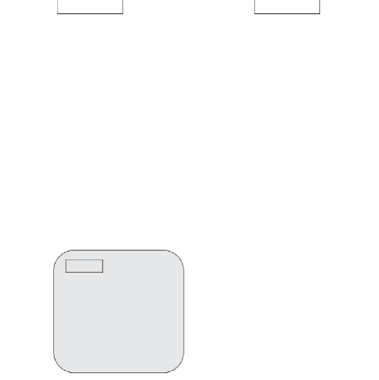
Logical
Physical
TABLES
FILES
CUSTOMER
ORDER
PAYMENT
PRODUCT
FLOWER
ARRANGEMENT
CHANNEL
GROWER
SHIPMENT
ROWS
COLUMNS
RECORDS
PRIMARY
KEYS
FIELDS
FOREIGN
KEYS
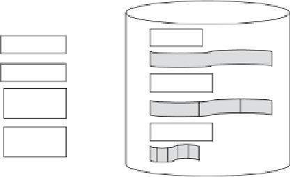
Figure 12-2
Logical design to physical design.
want to ensure adequate performance levels and provide for security and data
integrity. You want to design your data structures on storage in such a way as to
safeguard against any data loss.
Let us get back to the logical design for the florist business discussed in Chapter
11. How do you make the transition from this logical design to the physical design
for the database to support the business? What are the overall components of the
physical design? How do the components of the logical design map to those of the
physical design? Figure 12-2 portrays the transition to physical design from logical
design.
Examine the mapping of the components between logical design and physical
design. As a result of the logical design, you have tables or relations with columns
and rows for each table. These are the data as represented in the logical model for
a relational database system. Now, in physical storage, you have files and records


Search WWH ::

Custom Search