Geology Reference
In-Depth Information
dispersed
particles
concentration
profile
concentration
profile
concentrated
pumice lapilli
ash
cloud
velocity
profile
velocity
profile
boundary layer
moves up with time
concentration
velocity
concentration
velocity
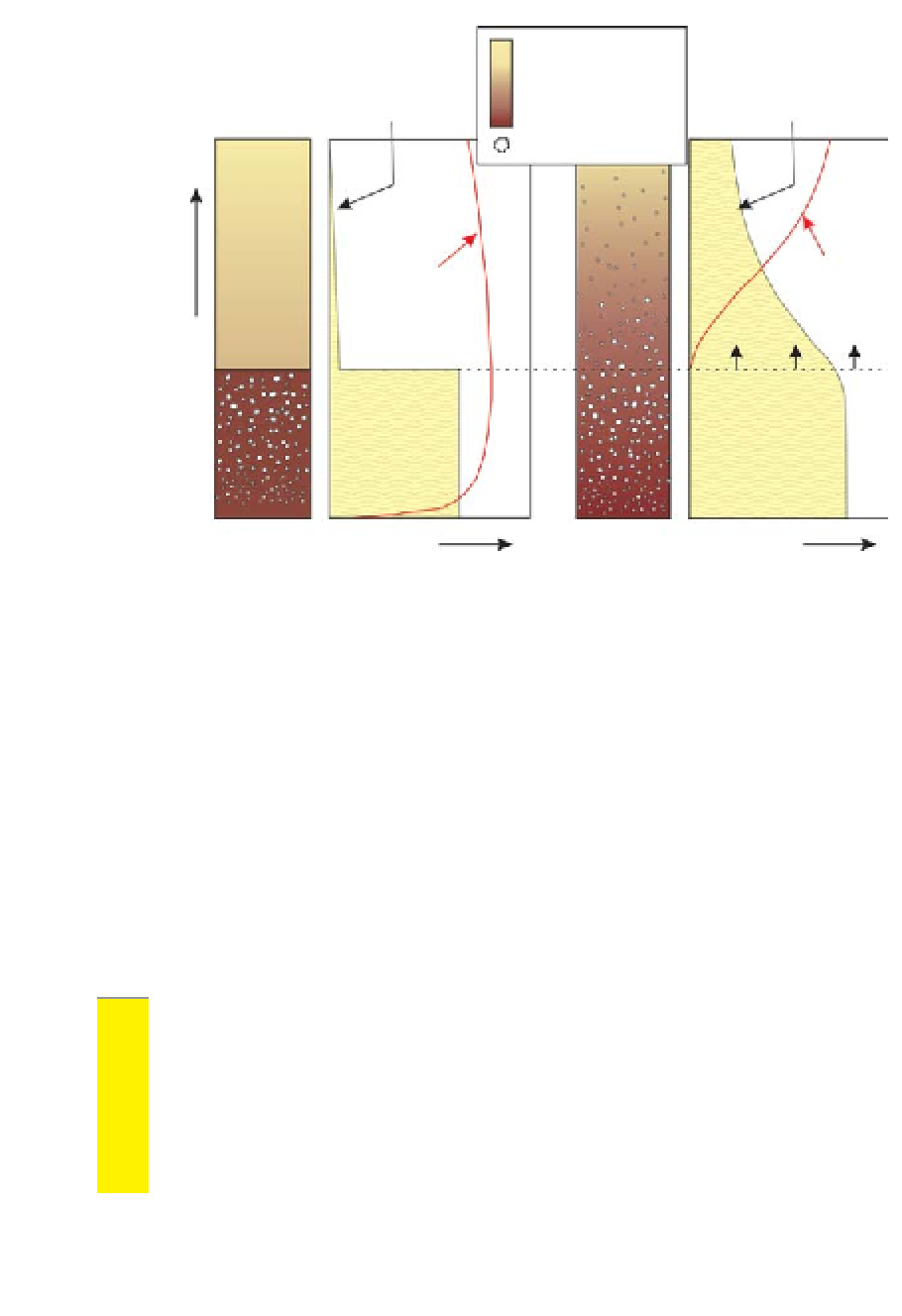
(a) Previous 'standard' model
(b)
Recent 'progressive
aggradation' model
Figure 5.15
Schematic showing the previous and more recent models of ign-
imbrite emplacement from pyroclastic flows.
by early cementation/vapour phase alteration. A typical section through an ign-
imbrite is given in the schematic log in Figure 5.16. Here a basal ground layer
commonly of fall out is followed by a basal deposit from a low concentration
lateral blast (may also be termed surge in some literature), followed by the
main ignimbrite deposit, a poorly-sorted mixture of lithics and pumice which
may show an increase in pumice concentration and size towards the top of the
deposit, which is normally capped by an ash sequence of varying size, sorting
and structure, known as the co-ignimbrite ash. A field example of a non welded
ignimbrite is given in Figure 5.17.
Welded ignimbrites
are characterised by having a wholly or partly welded part
of the deposit, which results from the deposit being very hot during deposition.
In extreme circumstances the whole deposit may be so hot that it fuses back
together to the characteristics of a lava of similar composition. Such ignimbrites
are known as
rheomorphic
. More commonly the central/lower part of the flow
becomes indurated and welded/intensely welded, displaying a
eutaxitic
texture
known as
fiamme
(flattened pumice) in the densely welded parts. In extreme