Image Processing Reference
In-Depth Information
Master
Node
Node
Node
Time
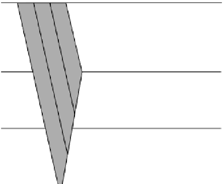
FIGURE .
EtherCAT timing.
TABLE .
Performance Indicators for SERCOS
Performance indicator
Profile /
a
Profile /
b
Delivery time
<
. µs
<
µs
Number of end-stations
≤
≤
Number of switches between end-stations
Throughput RTE
. M octets/s
≤
. M octets/s
Non-RTE bandwidth
%
%
Time synchronization accuracy
—
—
Non-time-based synchronization accuracy
<
µs
<
µs
Redundancy recovery time
a
Scenario with minimum cycle time and high-performance synchronization.
b
Scenario with non-RTE bandwidth and low-performance synchronization.
This sequence of transmitting synchronization, RT-data telegrams, and IP telegrams is repeated
every communication cycle. Defined values a for a communication cycle are ., ., ,
µs,andintegermultiplesofupto,µs.hetimeslotsfortheRTchannel,theIPchannel,
and the transmission time of the AT are transmitted during initialization and are therefore known to
each slave. In every device, a special software, or for a higher performance a field-programmable gate
array (FPGA),
∗
willbeneededwhichseparatestheRTchannelfromtheIPchannel.Performance
indicators for two typical setups are listed in Table ..
The application model of SERCOS is based on the drive model
†
with a cyclic data exchange.
This exchange includes status and actual values transmitted from the drive to the controller, and
commands and set points from the controller to the drive. The functionality of the drive device is
determined by setting different parameters in the model [].
∗
FPGA, a gate array is a prefabricated circuit, with transistors and standard logic gates.
†
A drive model consists of a controller and one or several drives (e.g., motors, servos).