Image Processing Reference
In-Depth Information
17.8 System Definition Process
Defining optimal signals packing and schedule table(s) fulfilling signalling needs in varying modes of
operation, with consideration of capabilities of the participating nodes is called the System Deinition
Process. Typically, it will result in generation of the LDF file, written by hand for simple systems, or
generated by high-level network design tools.
However, reusing existing, preconfigured slave nodes to create a cluster of them, starting from
scratch is not that convenient. This is especially true if the defined system contains node address
conflicts or frame identifier conflicts. The LIN Node Capability Language, which is a new feature
in LIN ., provides a standardized syntax for specification of off-the-shelves slave nodes. his will
simplify procurement of standard nodes as well as provide possibilities for tools that automate cluster
generation. he availability of such nodes is expected to grow rapidly. If accompanied by an NCF, it
will be possible to generate both the LIN configuration file, and initialization code for the master
node. hus, true plug-and-play with nodes in a cluster will become a reality.
By receiving an NCF, with every existing slave node, the system definition step is automatic: Just
add the NCF files to your project in the system definition tool and it produces the LDF file together
with C code to configure a conflict free cluster. he configuration C code shall, of course, be run in
the master node during start up of the cluster.
If you want to create new slave nodes as well, the process becomes somewhat more complicated.
The steps to perform will depend on the system definition tool being used, which is not part of the
LIN specification. A useful tool will allow for entering of additional information before generating
theLDFile.(ItisalwayspossibletowriteaictiveNCFileforthenon-existentslavenodeandthus,
it will be included.)
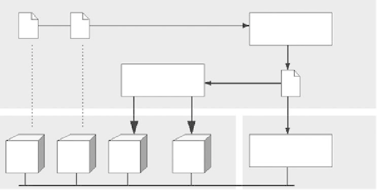
An example of the intended workflow is depicted in Figure .:
The slave nodes are connected to the master forming a LIN cluster. The corresponding NCF are
parsed by the System Defining Tool to generate an LDF in the system definition process. he LDF is
parsed by the System Generator to automatically generate LIN related functions in the desired nodes
(the Master and Slave in the example shown in Figure .). The LDF is also used by a LIN bus
analyzer/emulator tool to allow for cluster debugging.
NCF
Design
System defining
tool
System
generator
LDF
System
Debugging
Bus analyzer and
emulator
Slave 1
Slave 2
Slave 3
Master
LIN
FIGURE .
Workflow.