Image Processing Reference
In-Depth Information
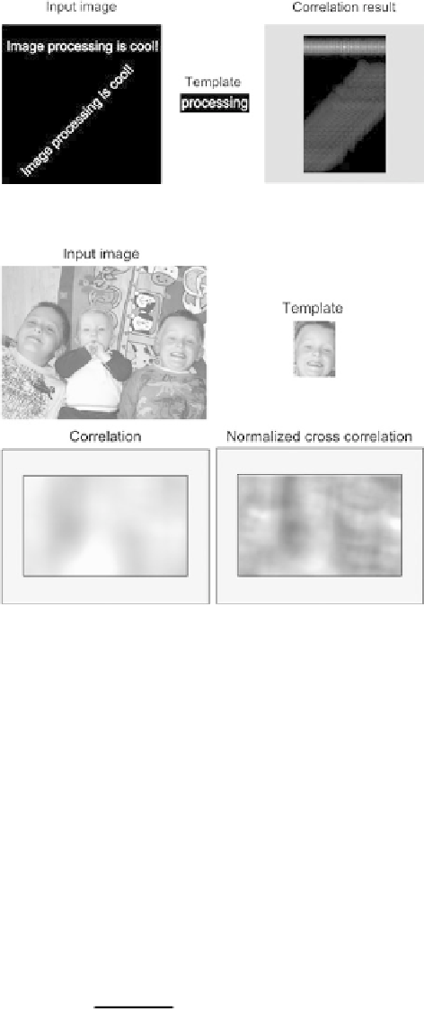
Fig. 5.9
Template matching
performed by correlating the
input image with a template.
The result of template
matching is seen to the
right
.
The
gray outer
region
illustrates the pixels that
cannot be processed due to
the border problem
Fig. 5.10
Template
matching using correlation
and normalized
cross-correlation. The
gray
regions
illustrate the pixels
that cannot be processed due
to the border problem
and in this particular case impossible, to actually find the position of the object by
looking at the values in the output image.
To avoid this problem we need to normalize the values in the output so they are
independent of the overall level of light in the image. To assist us in doing so we
use a small trick. Let us denote the template
H
and the image patch
F
. These are
both matrices, but by rearranging we can easily convert each matrix into a vector by
concatenating each row (or column) in the matrix, i.e.,
H
and
F
.
If we now look at correlation in terms of this vector representation, we can see
that Eq.
5.4
is actually the dot product between the two vectors, see Appendix B.
From geometry we know that the dot product between two vectors can be normal-
ized to the interval
[−
1
,
1
]
using the following equation:
H
•
F
|
H
|·|
F
|
cos
θ
=
(5.5)