Image Processing Reference
In-Depth Information
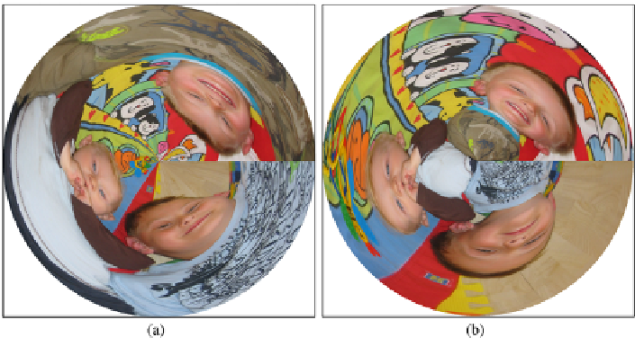
Fig.11.10
(
a
) A polar transformed image. (
b
) A polar transformed image with the y-axis pointing
upwards
where
r
max
is half the height of the output image. When
r>r
max
we simply say
g(x
,y
)
255. In Fig.
11.10
two polar images are illustrated. The first is calcu-
lated as described above. For the other one the y-axis (the radius) is pointing up as
opposed to down.
=
11.2.2 Twirl Transformation
Geometric transformations can easily become so complicated that the backward
mapping is very hard or even impossible to derive. Such transformations are there-
fore often defined directly in the output domain, meaning that the forward mapping
is
not
defined but only the backward mapping. The next three transformations are
of this type. The first is the
twirl transformation
, which is inspired by the polar
transformation, see Eqs.
11.1
and
11.2
. The rotation angle
θ
is now defined as
arctan
y
x
r
max
−
r
θ
=
+
φ
·
(11.11)
r
max
where
φ
is the rotation baseline and the other parameters are defined as for the polar
transformation. The effect of the transformation is that the center remains at the
same position and the rest of the pixels are rotated around the center with a rotation
angle that is maximum (
φ
degrees) near the center and becomes smaller the closer
to the image corners a pixel is. The final backward mapping is defined as
x
=
x
c
+
r
·
cos
(θ)
(11.12)
y
=
y
c
+
r
·
sin
(θ)
(11.13)