Image Processing Reference
In-Depth Information
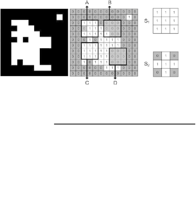
Fig. 6.4
A binary image illustrated both by colors (black and white) and numbers (0 and 1). A, B,
C and D illustrate four 3
×
3 image regions centered at: A:
f(
3
,
3
)
,B:
f(
7
,
3
)
,C:
f(
3
,
7
)
and D:
f(
8
,
8
)
. Lastly two different 3
×
3 structuring elements are illustrated
Table 6.1
Results of
applying the two structuring
elements (
SE
)inFig.
6.4
to
the input image in Fig.
6.4
at
four positions: A, B, C, and D
Position
SE
Fit
Hit
A
S
1
No
Yes
A
S
2
No
Yes
B
S
1
No
Yes
B
S
2
No
No
C
S
1
Ye s
Ye s
C
S
2
Ye s
Ye s
D
S
1
No
No
D
S
2
No
No
6.2
Level 2: Dilation and Erosion
At the next level Hit or Fit is applied to every single pixel by scanning through the
image as shown in Fig. 4.28. The size of the structuring element in these operations
has the same importance as the kernel size did in the previous chapter. The bigger the
structuring element, the bigger the effect in the image. As described in the previous
chapter we also have the border problem present here and solution strategies similar
to those listed in Sect. 5.1 can be followed. For simplicity we will ignore the border
problem in this chapter.
6.2.1 Dilation
Applying Hit to an entire image is denoted
Dilation
and is written as
g(x,y)
=
f(x,y)
⊕
SE
(6.1)