Environmental Engineering Reference
In-Depth Information
14×14
17×17
15×15
18×18
16×16
4.2
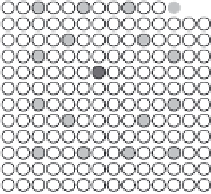
Layouts of different PWR FA design. Rods marked with light grey
colour are GTs into which the control rod cluster is inserted. The
position marked by a dark grey fi lled circle is the IT position (Cox
et al.
,
2006). (Source: A.N.T. International, 2011.)
Cook 1, which is switching to 17 × 17 through changing the reactor internals.
Figure 4.2 shows the current PWR fuel rod array designs.
In most PWRs, the assemblies are positioned in the core by bottom and top
fi ttings, and the lateral clearances are restricted by the assembly-to-assembly
contacts at the spacer-grid levels (Cox
et al
., 2006). Furthermore, the control
rods consist of rod cluster control assemblies (RCCAs), the poison part of
which moves into guide thimbles (GTs). These guide thimbles are an inte-
gral part of the assembly structure.

Search WWH ::

Custom Search