Geoscience Reference
In-Depth Information
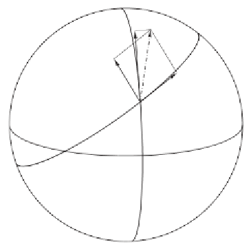
pole
-1
r
@
R
@#
W
T
®
satellite
1
r sin
#
@
R
@¸
®
90° -
#
i
node
Fig. 7.4. Components of the perturbing force
The components
T
and
W
are obtained from them by a plane rotation
(Fig. 7.4):
1
r
∂R
∂ϑ
1
r
sin
ϑ
∂R
∂λ
T
=
−
cos
α
+
sin
α,
(7-15)
∂R
∂ϑ
∂R
∂λ
1
r
1
r
sin
ϑ
W
=
−
sin
α
−
cos
α.
From the rectangular spherical triangle in Fig. 7.4 it follows that
cos
α
=
cos(
ω
+
v
)sin
i
sin
ϑ
cos
i
sin
ϑ
,
,
sin
α
=
(7-16)
so that finally
cos(
ω
+
v
)sin
i
r
sin
ϑ
∂R
∂ϑ
+
cos
i
r
sin
2
ϑ
∂R
∂λ
,
T
=
−
(7-17)
cos
i
r
sin
ϑ
∂R
∂ϑ
−
cos(
ω
+
v
)sin
i
r
sin
2
ϑ
∂R
∂λ
.
W
=
−
We have included
∂R/∂λ
because of the presence of longitude-dependent
tesseral harmonics in the general case (see Sect. 7.5). In our present case,
where
R
is given by (7-12),
∂R/∂λ
is zero.
Now we must differentiate (7-12) with respect to
r
and
ϑ
, compute the
components
S
,
T
,
W
from Eqs. (7-13) and (7-17), and substitute them
into the system (7-10). In this way, we can express the rates of change
a, e, ...
of the orbital elements in terms of the coecients
J
2
,J
3
,J
4
, ... .
We