Graphics Reference
In-Depth Information
Rotation
∂
ζ
Translation
∂
x
r
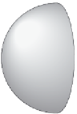
Figure 2.10
Light-dark sphere model around a surface element. (After [Ward et al. 88].)
above the surface point
(
Figure 2.10
)
. Then they look at how the irradiance
changes when the sphere is rotated or translated. The reasoning is that this causes
as much of a change as any real incoming radiance, so an error bound for this case
bounds that of any real radiance distribution.
More precisely, the goal is to express the change in irradiance as a function of
the sphere rotation angle
and the displacement
x
. The exact formula is messy,
but a first-order Taylor series expansion serves as a reasonable approximation:
ζ
.
∂
E
x
0
)+
∂
E
∂ζ
(
ζ
−
ζ
0
)
ε
≤
x
(
x
−
(2.8)
∂
Inside the disc of radius
R
i
,
4
π
E
R
|
ε
≤
x
−
x
0
|
+
E
|
ζ
−
ζ
0
|.
(2.9)
The right side of Equation (2.9) can be viewed as the maximum irradiance gra-
dient inside the disc. The change in irradiance caused by translating and rotating
the sphere at a point is equivalent to the irradiance at a nearby point. Let
P
i
denote
the original point and
N
i
the surface normal at
P
i
. At a nearby point
P
,wherethe
surface normal is
N
, Equation (2.9) can be expressed as
P
−
P
i
⎡
⎤
2
4
π
ε
(
P
⎣
2
N
(
P
)
·
N
(
P
i
)
⎦
,
)
≤
E
i
+
−
(2.10)
R
i
and this represents the maximum variation of the irradiance in the disc. The ir-
radiance recorded at
P
i
is considered usable in the disc when this variation is
sufficiently small.