Graphics Reference
In-Depth Information
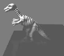
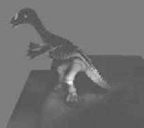
Figure 10.26
Transfer basis vectors (radiance transfer modes). (From [James and Fatahalian 03]
c
2003
ACM, Inc. Included here by permission.)
precomputed transfer is thus limited to these points, and the PRT vectors form the
reduced appearance model. For given state
j
, the radiance transfer field is com-
puted as the weighted sum of the radiance transfer field precomputed at all the
representative states
N
a
k
=
1
w
k
q
a
to the difference of the shapes at state
k
and state
j
. The advantage of this method
is that the result of the interpolation reflects the changes of the shape over the
entire deformation.
q
a
=
Cluster
Na
Cluster
k
Cluster 2
r
N
a
∞
Cluster 1
r
k
r
2
r
1
w
k
r
1
State to be synthesized
Representative states
Figure 10.27
Interpolation of radiance transfer fields.
10.3.5 Run-time Synthesis
Through the preprocess described in this section, each IRF orbit stores both the
reduced shape coordinates
q
u
and the reduces appearance coordinates
q
a
at each