Graphics Reference
In-Depth Information
Environment light
M
p
Exit Transfer Matrix
B
BRDF Matrix
Outgoing
light
R
p
Rotation Matrix
T
p
Transfer Matrix
S
p
Subsurface Scattering Matrix
p
Subsurface scattering
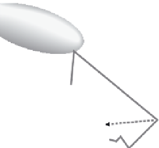
Figure 10.13
Exit radiance transfer conceptual diagram. (After [Sloan et al. 03a].)
John Hart, and John Snyder introduced a local PCA method for PRT in the pa-
per entitled “Clustered Principal Components for Precomputed Radiance Trans-
fer” [Sloan et al. 03a].
1
Figure 10.13 illustrates the conceptual process of exit radiance transfer simu-
lation described in the 2003 paper. In addition to employing local PCA, transfer
matrices are generalized to include both interreflection and subsurface scattering.
The layered method described in Chapter 4 is used to compute the subsurface
scattering component. It is diffuse, and therefore view-independent, so it only
affects the constant term of the outgoing radiance SH expansion. This subsurface
scattering component can be expressed as a transfer matrix, but only the top ele-
ments (corresponding to the constant SH terms) will be nonzero. The actual exit
transfer matrix is therefore
BR
p
T
p
+
S
p
,
although in practice the subsurface scattering is normally handled separately.
2
Figure 10.14 contains examples of renderings using precomputed transfer ma-
trices with the local PCA compression. From left to right, more basis elements are
used to represent each cluster. The rightmost images are the result of rendering
using the actual exit transfer matrix on each sample point; i.e., PCA is not ap-
1
This paper introduced Leen's PCA algorithm into computer graphics; the application to BTF data
described in Chapter 9 actually came later.
2
The fact that the reflection integral is actually performed over the hemisphere rather than the
sphere is handled by the clipping function max
implicit in the SH expansion. This is not so
easy to approximate with spherical harmonics. Sloan et al. use a separate matrix
A
−
1
to “boost” the
BRDF matrix and improve the approximation, especially at silhouette edges. The actual exit transfer
matrix is
A
−
1
BA
−
1
R
p
T
p
.
(
cos
θ
,
0
)