Graphics Reference
In-Depth Information
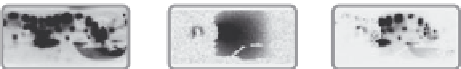
(a)
(b)
(c)
Rendering
result of
point
P
Sum all
pixels in (c)
HDR
environment map
Reflection
function for point
P
The product of all
pixels in (a) and (b)
Figure 8.28
Rendering using reflectance functions. (After [Debevec et al. 00].)
To render a point
p
on the surface of an object illuminated by a point light
source in direction
, the reflectance function pixel value is just multiplied
by the radiance of the source. The corresponding pixels across the surface of the
object so multiplied collectively produce an image of the object as if it were lit
by the source. To render the point using an HDR environment map, each value in
the reflectance function for
p
is multiplied by the value of the environment map
from the corresponding direction (
Figure 8.28
)
. Pixels in an HDR environment
map can be arranged to match the arrangement of
(
θ
i
,
φ
i
)
φ
i
directions in each
reflectance function, which simplifies this process, and also makes it more suit-
able for hardware implementation. The sampling density of the environment map
may be much larger than the density of the spotlights, in which case the environ-
ment map pixels need to be downsampled so that pixels in the reflectance function
match pixels in the filtered environment map. Just as pixels in the environment
map can be regarded as point sources, a point source can be regarded as a pixel
in the environment map. An environment map for a single point source has just
one nonzero pixel—the one corresponding to the source. Regardless of the il-
lumination, the reflectance field includes all the local interreflection, shadowing,
and subsurface scattering. It is indeed remarkable that all these effects can be
accounted for by simple multiplications.
θ
i
and
8.2.4 Acquiring a Facial Reflectance Field
The method described in the previous subsection only works for a single view-
point, i.e., a fixed
φ
r
. In order to acquire the complete reflectance field, the
process has be repeated for a set of different viewpoints. That is, the camera must
be moved and another set of HDR images captured for each of the spotlights in
the light stage. Unfortunately, the subject has to sit perfectly still throughout the
entire acquisition process, which puts a practical limit on the number of camera
positions. The density of viewpoints is much lower than the density of spotlights.
The authors of the “reflectance field” paper refer to the process of interpolat-
ing viewpoints as “synthesizing” the reflectance field from an arbitrary viewing
position. This process involves finding pixel correspondences between images:
θ
r
and