Graphics Reference
In-Depth Information
(a)
(b)
(c)
(d)
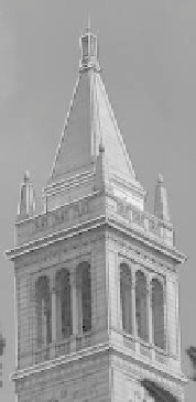
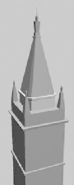
Figure 5.9
Recovering an architectural model. (a) The user starts by marking lines in the images that
corresponds to edges of the rough model, which is shown in (b). The accuracy of the
model is checked by projecting the captured image onto the model. (d) A rendering of the
completed model with view-dependent texture maps. (From [Debevec et al. 96].)
the recovered model, and part (c) shows the projection onto the image. Only one
of the lower pinnacles has been marked; the model geometry assures that it is
replicated properly at the other three corners.
The reconstruction algorithm described in the paper works by matching the
model edges to corresponding observed edges in the images, which have been
manually selected by the user. Figure 5.10(a) illustrates the projection of a 3D
scene edge projected onto the image plane of a captured image. The line con-
taining the projected edge is the intersection of the image plane with the plane
through the 3D line and the camera viewpoint. The camera coordinate system is
represented by a rotation matrix
R
and a translation vector
t
;if
v
is the direction
vector of the 3D line and
d
is any point on the line, then the normal vector to the
plane is
×
(
d
−
t
m
=
R
(
v
))
.
(5.3)
The reconstructionworks by choosing parameters to simultaneouslyminimize
the disparity of all the predicted model edges and the corresponding observed
edges. Figure 5.10(b) shows how this error is computed in an image plane. The
model edge is projected onto the image plane, and the the error is the integral
of the distance between the edge line and the observed edge over the length of
the observed edge. The camera parameters
R
and
t
are not known, so these are