Geoscience Reference
In-Depth Information
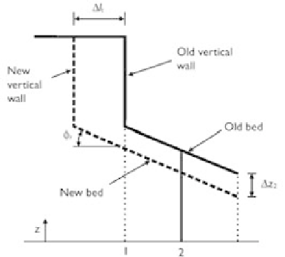
Figure 7.17
Headcut migration due to toe scour.
p
0.4
c
−
ρ
b
/ρ
2
; and
m
−
3
). At each time step
M
=
/(
1
)
ρ
s
is the soil density (kg
·
t
,
s
Eq. (7.71) gives the headwall retreat length
l
s
due to hydraulic shear.
The sediment transport in the plunge pool, which is highly affected by the rapidly-
varied jet impinging flow, is simulated using the 3-D model introduced in Section 7.3
with the sediment transport capacity determined using Eqs. (3.70) and (3.95) with the
corrections described in Eqs. (7.63) and (7.68). From this calculation, the bed change
z
2
at the center of the first control volume near the toe of headwall surface at the
time step
t
can be obtained, and then, the headcut retreat length due to this toe scour
is given as
l
t
=
z
2
/
tan
φ
r
, as shown in Fig. 7.17. Here,
φ
r
is the repose angle of
sediment. The actual headcut migration length is the larger of
l
t
.
The time-averagedmodel described above simulates the headcut migration caused by
the headwall surficial erosion and toe erosion. These two erosion modes are the main
factors of headcut migration, as they induce the mass failure and wash out the wasted
sediment debris. Therefore, this time-averaged model can acquire the main features of
headcut migration.
The headcut boundary propagates upstream and expands sideward. A moving grid
technique is implemented to capture this moving boundary in the horizontal directions,
combined with the original one to track the water surface change and bed deformation
in the vertical direction. At each time step or iteration step, the computational grid is
adjusted after the calculations of water level, bed deformation, and headcut migration.
The established headcut migration model was tested by Wu and Wang (2005) using
the experiments of Bennett
et al
. (1997). The experiments were carried out in a flume
5.5m long. The test part was a cavity 2m long and 0.165m wide, filled with 0.25m
deep soil. The bed slope of the flume was 1%. The used soil was the parent material
of the Ruston silt loam after being crushed and air-dried and consisted of 20.0% clay,
2.9% silt, and 77.1% sand. A preformed 0.025m high headcut was constructed at
the downstream end of the cavity. Application of simulated rain produced a surface
seal layer to negate any detachment of the soil material by the subsequent overland
l
s
and