Geoscience Reference
In-Depth Information
6.3.5 Channel meandering process
To simulate the channel meandering process, a depth-averaged 2-D model must be
capable of: (1) considering the helical flow effect in meandering channels; (2) sim-
ulating bank erosion; and (3) handling the moving boundary problem. Because the
channel meandering process is usually much slower than the sediment transport and
bed change processes, the aforementioned strategies of considering the helical flow
effect in curved channels with fixed banks can be applied in the simulation of flow
and sediment transport in meandering channels.
Erosion mechanisms differ for banks with cohesive and non-cohesive materials. For
a cohesive bank, the bank material fails in blocks. The bank erosion models described
in Section 5.3.6.1 for the 1-D simulation can be extended to the depth-averaged 2-D
simulation. Bank-toe erosion can be computed using the method of Arulanandan
et al
.
(1980), and mass failures can be calculated using the method of Osman and Thorne
(1988) or Simon
et al
. (2000). These are not repeated here.
For a non-cohesive bank, the bank material fails in particles. Once the bank slope
exceeds the repose angle, the bank particles will slide to the bank toe and form a new
slope with the repose angle. In the simulation of this sliding process, mass conservation
should be satisfied. The following algorithm is recommended for handling the non-
cohesive bank sliding process. It is also applicable to the sliding of a non-cohesive bed
with a steep slope.
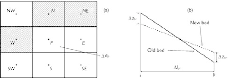
Consider a cluster comprising of the cell centered by point
P
and eight adjacent
cells, shown in Fig. 6.18(a). If the slope between point
P
and one of the eight adjacent
points exceeds the repose angle, the bank particles will slide and form a new bank slope
with the repose angle between the two points. Fig. 6.18(b) shows the sliding process
between point
P
and an adjacent point denoted as
i
. This process can be described
mathematically by
(
z
bi
+
z
bi
)
−
(
z
bP
+
z
bP
)
=±
tan
φ
(6.99)
r
l
Pi
where
z
bP
and
z
bi
are the bed elevations at points
P
and
i
;
z
bP
and
z
bi
are the
changes in bed elevations due to sliding;
l
Pi
is the distance between points
P
and
Figure 6.18
Non-cohesive bank sliding model: (a) plan view; (b) side view.