Geoscience Reference
In-Depth Information
Applying Eq. (5.46) in the reaches from cross-sections 1 and 2 to 3 yields
Q
3
|
β
1
Q
1
=
β
3
Q
3
β
3
Q
3
2
gA
3
−
β
1
Q
1
+
x
13
2
Q
3
|
K
3
Q
1
|
Q
1
|
K
1
2
gA
1
+
z
s
1
2
gA
3
+
z
s
3
+
+
λ
13
2
gA
1
(5.49)
Q
3
β
2
Q
2
2
gA
2
+
=
β
3
Q
3
β
3
Q
3
2
gA
3
−
β
2
Q
2
+
x
23
2
|
Q
3
|
Q
2
|
Q
2
|
z
s
2
2
gA
3
+
z
s
3
+
+
λ
23
K
3
K
2
2
gA
2
(5.50)
where
x
13
and
x
23
represent the distances from cross-sections 1 and 2 to
3, respectively.
If the flow is subcritical, the water stage
z
s
3
at cross-section 3 is obtained first
by backwater calculation in channel 3. The water stages
z
s
1
and
z
s
2
at cross-sections
1 and 2 can then be obtained by solving Eqs. (5.49) and (5.50), following the procedure
introduced in Section 5.2.1.2.
As a simplified case, if the distances
x
23
are very small, the water stages
or energy heads of the three cross-sections at the confluence can be assumed to be
identical. Thus, the calculated water stage at cross-section 3 is specified to cross-
sections 1 and 2 if the flow is subcritical.
If the flow is supercritical, the forewater calculations are carried out in channels
1 and 2 down to cross-sections 1 and 2. The reach controlling the flow at the confluence
has a larger specific force
A
x
13
and
z
s
is the depth from the
water surface to the centroid of the flow area. The forewater calculation is made from
the controlling upstream cross-section down to cross-section 3.
z
s
¯
+
β
QU
/
g
(Chow, 1959). Here,
¯
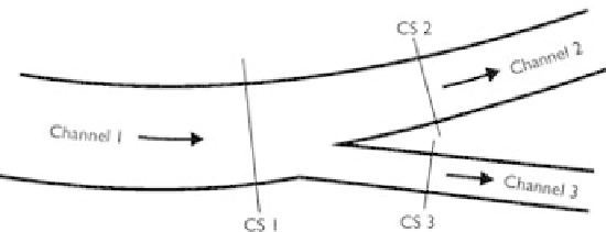
Channel splits
A split of one channel to two channel branches is depicted in Fig. 5.10, in which cross-
section 1 is placed at the end of the upstream channel (denoted as 1), and cross-sections
2 and 3 are at the beginnings of the downstream channels (denoted as 2 and 3). The
continuity equation at the channel split reads
Q
2
+
Q
3
=
Q
1
(5.51)
Figure 5.10
Configuration of channel split.