Geoscience Reference
In-Depth Information
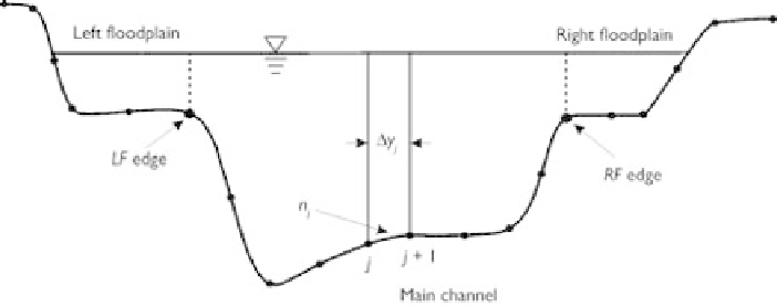
Figure 5.4
Representation of compound cross-section with floodplains.
where the subscript
LF
denotes the left floodplain,
MC
the main channel, and
RF
the
right floodplain.
For each subsection, the Manning
n
can be determined using the hydraulic radius
or energy slope division method. For example, the Manning
n
in the main channel is
determined using these two methods as follows:
⎛
⎞
⎛
⎞
2
/
3
1
/
2
j
=
RCB
j
=
RCB
LCB
χ
j
n
3
/
2
⎝
⎠
⎝
LCB
χ
j
n
j
/χ
MC
⎠
n
MC
=
/χ
MC
,
n
MC
=
(5.25)
j
j
=
j
=
where
LCB
and
RCB
represent the main-channel panels adjacent to the left and right
floodplain edges (denoted as
LF
and
RF
in Fig. 5.4), respectively.
5.1.1.5 Momentum correction factor
The correction factor
for momentum in Eq. (5.2) is close to 1 for a simple cross-
section. For the compound cross-section shown in Fig. 5.4,
β
β
is determined by
1
QU
1
QU
(
u
2
dA
β
=
=
Q
LF
U
LF
+
Q
MC
U
MC
+
Q
RF
U
RF
)
A
K
LF
K
2
MC
K
RF
A
RF
A
K
2
=
A
LF
+
A
MC
+
(5.26)
5.1.2 Formulation of 1-D sediment transport model
5.1.2.1 1-D non-equilibrium sediment transport equations
For general applications, the transport of non-uniform total load is considered here.
Because the total load can be divided into bed load and suspended load, or into