Hardware Reference
In-Depth Information
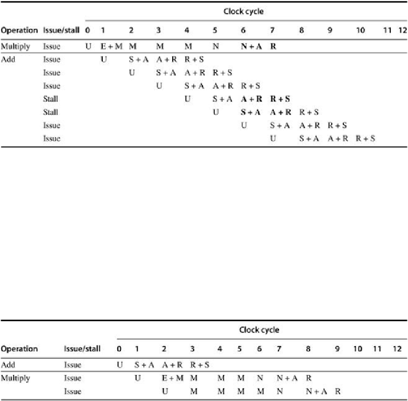
FIGURE C.48
An FP multiply issued at clock 0 is followed by a single FP add issued
between clocks 1 and 7
. The second column indicates whether an instruction of the speci-
fied type stalls when it is issued n cycles later, where n is the clock cycle number in which the
U stage of the second instruction occurs. The stage or stages that cause a stall are in bold.
Note that this table deals with only the interaction between the multiply and
one
add issued
between clocks 1 and 7. In this case, the add will stall if it is issued 4 or 5 cycles after the mul-
tiply; otherwise, it issues without stalling. Notice that the add will be stalled for 2 cycles if it is-
sues in cycle 4 since on the next clock cycle it will still conflict with the multiply; if, however,
the add issues in cycle 5, it will stall for only 1 clock cycle, since that will eliminate the con-
flicts.
FIGURE C.49
A multiply issuing after an add can always proceed without stalling,
since the shorter instruction clears the shared pipeline stages before the longer in-
struction reaches them
.
Search WWH ::

Custom Search