Hardware Reference
In-Depth Information
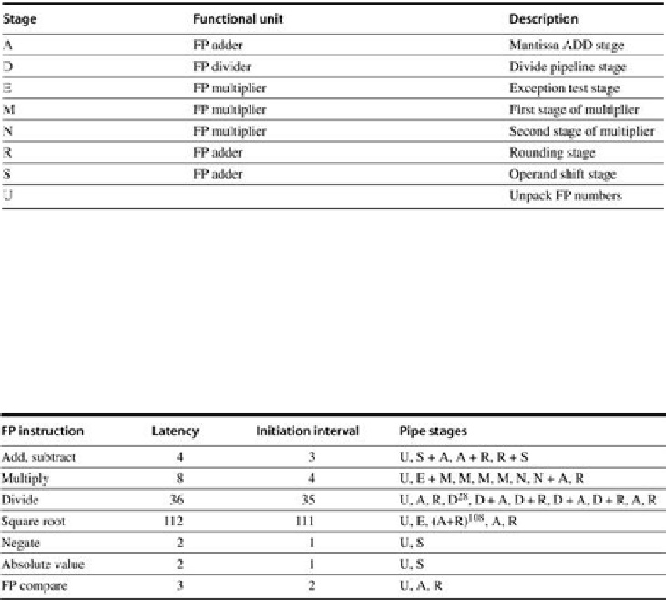
FIGURE C.46
The eight stages used in the R4000 floating-point pipelines
.
There is a single copy of each of these stages, and various instructions may use a stage
zero or more times and in different orders.
Figure C.47
shows the latency, initiation rate, and
pipeline stages used by the most common double-precision FP operations.
FIGURE C.47
The latencies and initiation intervals for the FP operations both depend
on the FP unit stages that a given operation must use
. The latency values assume that
the destination instruction is an FP operation; the latencies are 1 cycle less when the destina-
tion is a store. The pipe stages are shown in the order in which they are used for any opera-
tion. The notation S + A indicates a clock cycle in which both the S and A stages are used.
The notation D
28
indicates that the D stage is used 28 times in a row.
From the information in
Figure C.47
, we can determine whether a sequence of different, in-
dependent FP operations can issue without stalling. If the timing of the sequence is such that a
conlict occurs for a shared pipeline stage, then a stall will be needed.
Figures C.48
,
C.49
,
C.50
,
and C.51
show four common possible two-instruction sequences: a multiply followed by an
add, an add followed by a multiply, a divide followed by an add, and an add followed by a
divide. The figures show all the interesting starting positions for the second instruction and
whether that second instruction will issue or stall for each position. Of course, there could be
three instructions active, in which case the possibilities for stalls are much higher and the ig-
ures more complex.
Search WWH ::

Custom Search