Hardware Reference
In-Depth Information
FIGURE C.42
The structure of the R4000 integer pipeline leads to a 2-cycle load delay
.
A 2-cycle delay is possible because the data value is available at the end of DS and can be
bypassed. If the tag check in TC indicates a miss, the pipeline is backed up a cycle, when the
correct data are available.
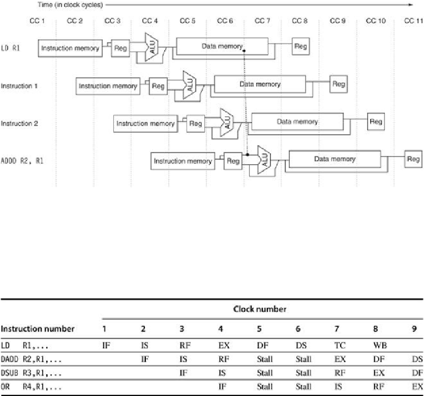
FIGURE C.43
A load instruction followed by an immediate use results in a 2-cycle stall
.
Normal forwarding paths can be used after 2 cycles, so the
DADD
and
DSUB
get the value by for-
warding after the stall. The
OR
instruction gets the value from the register file. Since the two in-
structions after the load could be independent and hence not stall, the bypass can be to in-
structions that are 3 or 4 cycles after the load.
Figure C.44
shows that the basic branch delay is 3 cycles, since the branch condition is com-
puted during EX. The MIPS architecture has a single-cycle delayed branch. The R4000 uses
a predicted-not-taken strategy for the remaining 2 cycles of the branch delay. As
Figure C.45
shows, untaken branches are simply 1-cycle delayed branches, while taken branches have a
1-cycle delay slot followed by 2 idle cycles. The instruction set provides a branch-likely in-
struction, which we described earlier and which helps in filling the branch delay slot. Pipeline
interlocks enforce both the 2-cycle branch stall penalty on a taken branch and any data hazard
stall that arises from use of a load result.
Search WWH ::

Custom Search