Hardware Reference
In-Depth Information
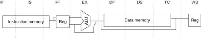
FIGURE C.41
The eight-stage pipeline structure of the R4000 uses pipelined instruc-
tion and data caches
. The pipe stages are labeled and their detailed function is described in
the text. The vertical dashed lines represent the stage boundaries as well as the location of
pipeline latches. The instruction is actually available at the end of IS, but the tag check is done
in RF, while the registers are fetched. Thus, we show the instruction memory as operating
through RF. The TC stage is needed for data memory access, since we cannot write the data
into the register until we know whether the cache access was a hit or not.
The function of each stage is as follows:
■ IF—First half of instruction fetch; PC selection actually happens here, together with initi-
ation of instruction cache access.
■ IS—Second half of instruction fetch, complete instruction cache access.
■ RF—Instruction decode and register fetch, hazard checking, and instruction cache hit de-
tection.
■ EX—Execution, which includes effective address calculation, ALU operation, and branch-
target computation and condition evaluation.
■ DF—Data fetch, first half of data cache access.
■ DS—Second half of data fetch, completion of data cache access.
■ TC—Tag check, to determine whether the data cache access hit.
■ WB—Write-back for loads and register-register operations.
In addition to substantially increasing the amount of forwarding required, this longer-
latency pipeline increases both the load and branch delays.
Figure C.42
shows that load delays
are 2 cycles, since the data value is available at the end of DS.
Figure C.43
shows the shorthand
pipeline schedule when a use immediately follows a load. It shows that forwarding is required
for the result of a load instruction to a destination that is 3 or 4 cycles later.
Search WWH ::

Custom Search