Hardware Reference
In-Depth Information
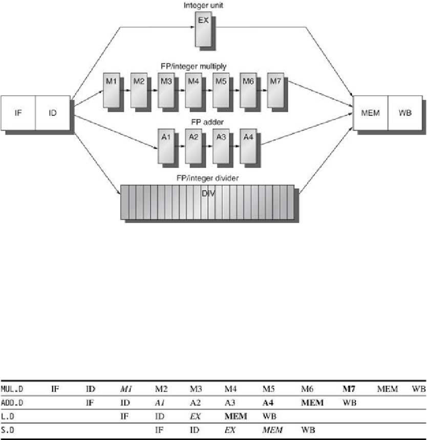
FIGURE C.35
A pipeline that supports multiple outstanding FP operations
. The FP mul-
tiplier and adder are fully pipelined and have a depth of seven and four stages, respectively.
The FP divider is not pipelined, but requires 24 clock cycles to complete. The latency in in-
structions between the issue of an FP operation and the use of the result of that operation
without incurring a RAW stall is determined by the number of cycles spent in the execution
stages. For example, the fourth instruction after an FP add can use the result of the FP add.
For integer ALU operations, the depth of the execution pipeline is always one and the next in-
struction can use the results.
FIGURE C.36
The pipeline timing of a set of independent FP operations
. The stages in
italics show where data are needed, while the stages in bold show where a result is available.
The ”
.D
” extension on the instruction mnemonic indicates double-precision (64-bit) floating-
point operations. FP loads and stores use a 64-bit path to memory so that the pipelining tim-
ing is just like an integer load or store.
The structure of the pipeline in
Figure C.35
requires the introduction of the additional
pipeline registers (e.g., A1/A2, A2/A3, A3/A4) and the modification of the connections to those
registers. The ID/EX register must be expanded to connect ID to EX, DIV, M1, and A1; we can
refer to the portion of the register associated with one of the next stages with the notation ID/
EX, ID/DIV, ID/M1, or ID/A1. The pipeline register between ID and all the other stages may
be thought of as logically separate registers and may, in fact, be implemented as separate re-
Search WWH ::

Custom Search