Hardware Reference
In-Depth Information
selves are expensive. While such features may be valuable for Internet setings, they are gen-
erally unused inside the datacenter.
WSC Memory Hierarchy
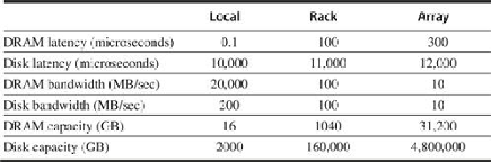
Figure 6.6
shows the latency, bandwidth, and capacity of memory hierarchy inside a WSC,
and
Figure 6.7
shows the same data visually. These figures are based on the following assump-
tions [
Barroso and Hölzle 2009
]
:
■ Each server contains 16 GBytes of memory with a 100-nanosecond access time and transfers
at 20 GBytes/sec and 2 terabytes of disk that offers a 10-millisecond access time and trans-
fers at 200 MBytes/sec. There are two sockets per board, and they share one 1 Gbit/sec Eth-
ernet port.
■ Every pair of racks includes one rack switch and holds 80 2U servers (see
Section 6.7
).
Networking software plus switch overhead increases the latency to DRAM to 100 micro-
seconds and the disk access latency to 11 milliseconds. Thus, the total storage capacity of a
rack is roughly 1 terabyte of DRAM and 160 terabytes of disk storage. The 1 Gbit/sec Eth-
ernet limits the remote bandwidth to DRAM or disk within the rack to 100 MBytes/sec.
■ The array switch can handle 30 racks, so storage capacity of an array goes up by a factor of
30: 30 terabytes of DRAM and 4.8 petabytes of disk. The array switch hardware and soft-
ware increases latency to DRAM within an array to 500 microseconds and disk latency to
12 milliseconds. The bandwidth of the array switch limits the remote bandwidth to either
array DRAM or array disk to 10 MBytes/sec.
FIGURE 6.6
Latency, bandwidth, and capacity of the memory hierarchy of a WSC [
Bar-
roso and Hölzle 2009
]
.
Figure 6.7
plots this same information.
Search WWH ::

Custom Search