Hardware Reference
In-Depth Information
■ Coherence Protocol Performance
■ Coherence Protocol Optimizations
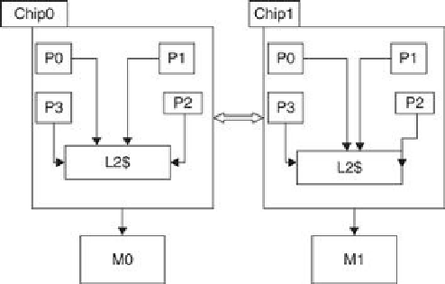
Consider the distributed shared-memory system illustrated in
Figure 5.37
.
It consists of two
four-core chips. The processor in each chip share an L2 cache (L2$), and the two chips are
connected via a point-to-point interconnect. The system memory is distributed across the two
cessor has a single direct-mapped L1 cache that holds two blocks, each holding two words.
Each chip has a single direct-mapped L2 cache that holds two blocks, each holding two words.
To simplify the illustration, the cache address tags contain the full address and each word
shows only two hex characters, with the least significant word on the right. The L1 cache states
are denoted M, S, and I for Modified, Shared, and Invalid. Both the L2 caches and memor-
ies have directories. The directory states are denoted DM, DS, and DI for Directory Modified,
Directory Shared, and Directory Invalid. The simple directory protocol is described in
Figures
is shared externally in another chip; for example,
P1,0;E
denotes that a line is shared by local
processor
P1,0
and is externally shared in some other chip. The memory directory has a list of
the chip sharers/owners of a line; for example,
C0,C1
denotes that a line is shared in chips 0 and
1.
FIGURE 5.37
Multichip, multicore multiprocessor with DSM
.
Search WWH ::

Custom Search