Hardware Reference
In-Depth Information
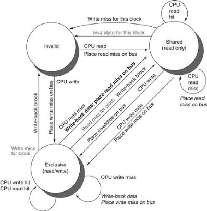
FIGURE 5.7
Cache coherence state diagram with the state transitions induced by the
local processor shown in black and by the bus activities shown in gray
. As in
Figure 5.6
,
the activities on a transition are shown in bold.
Although our simple cache protocol is correct, it omits a number of complications that make
the implementation much trickier. The most important of these is that the protocol assumes
that operations are
atomic
—that is, an operation can be done in such a way that no interven-
ing operation can occur. For example, the protocol described assumes that write misses can
be detected, acquire the bus, and receive a response as a single atomic action. In reality this
is not true. In fact, even a read miss might not be atomic; after detecting a miss in the L2 of a
multicore, the core must arbitrate for access to the bus connecting to the shared L3. Nonatomic
actions introduce the possibility that the protocol can
deadlock
, meaning that it reaches a state
where it cannot continue. We will explore these complications later in this section and when
we examine DSM designs.
With multicore processors, the coherence among the processor cores is all implemented on
chip, using either a snooping or simple central directory protocol. Many dual-processor chips,
including the Intel Xeon and AMD Opteron, supported multichip multiprocessors that could
be built by connecting a high-speed interface (called Quickpath or Hypertransport, respect-
Search WWH ::

Custom Search