Image Processing Reference
In-Depth Information
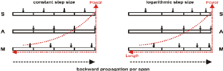
Fig. 9. Schemes of SSFM algorithms for DBP compensation. S: Symmetric-SSFM, A:
Asymmetric-SSFM, and M: Modified-SSFM. The red-dotted curves show the power
dependence along per-span length..
power exponentially decays along each fiber span, the step size is increased along the fiber.
If backward propagation is regarded, the high power regime locates in the end of each span,
illustrated in Fig. 1 by the red dotted curves and the step size has to be decreased along each
backward propagation span.
Note that the slope coefficient for logarithmic step-size distribution (see section 3.2.4 of this
chapter) has been chosen as 1 to reduce the relative global error according to (Jaworski, 2008).
The solid arrows in Fig. 9 depict the positions for calculating the non-linear phase. For the
symmetric scheme, the non-linearity calculating position (NLCP) is located in the middle of
each step. For the asymmetric scheme, NLCP is located at the end of each step. For the
modified scheme, NLCP is shifted between the middle and the end of each step and the
position is optimized to achieve the best performance (
?
).
In all schemes, the non-linear
phase was calculated by
γ
DBP
was optimized to obtain the best performance. All the algorithms were implemented for
DBP compensation to recover the signal distortion in a single-channel 16-QAM transmission
system with bit rate of 112Gbps (28Gbaud). In this simulation model, we used an 20x80km
single mode fiber (SMF) link without any inline dispersion compensating fiber (DCF). SMF has
the propagation parameters: attenuation
φ
NL
=
γ
DBP
·
P
·
L
eff
, where the non-linear coefficient for DBP
α
=0.2dB/km, dispersion coefficient
D
=16ps/nm-km
=1.2 km
−
1
W
−
1
. The EDFA noise figure has been set to 4dB and
and non-linear coefficient
α
PMD effect was neglected.
5.2 Simulation results
Fig. 10, compares the performance of all SSFM algorithms with varying number of steps per
span. In our results, error vector magnitude (EVM) was used for performance evaluation
of received 16-QAM signals. Also various launch powers are compared: 3dBm (Fig. 10(a)),
6dBm (Fig. 10(b)) and 9dBm (Fig. 10(c)). For all launch powers the logarithmic distribution
of step sizes enables improved DBP compensation performance compared to using constant
step sizes. This advantage arises especially at smaller number of steps (less than 8 steps
per span). As the number of steps per span increases, reduction of EVM gets saturated
and all the algorithms show the same performance. For both logarithmic and constant step
sizes, the modified SSFM scheme, which optimizes the NLCP, shows better performance than
symmetric SSFM and asymmetric SSFM, where the NLCP is fixed. This coincides with the
results which have been presented in
?
. However, the improvement given from asymmetric
to modified SSFM is almost negligible when logarithmic step sizes are used, which means