Image Processing Reference
In-Depth Information
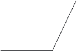
Fig. 24. COHBF approach to
demultiplexing
DF implementation with selectable transfer
functions;
N
o
i
,
d
i
=(
−
)
o
i
/2
;
o
i
∈{
=
11,
b
i
=(
−
)
}
∈{
}
1
1
0, 1, 2, 3
,
i
I, II
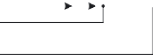
Fig. 25. DF separator: Sign-setting for selection of desired channel transfer functions
(
−
)
the COHBF approach to DF implementation a total of
/2 delays are needed (not
counting shimming delays,
z
−
1
, and the two superfluous delays at the input nodes of the
outer delay chains, indicated in grey).
Finally, we want to show and emphasise the simplicity of the channel selection procedure.
There is a total of 8 summation points, the inner 4 lattice output nodes A, B, C, and D, and the
4 system output port nodes, where the signs of some input sequences of the output port nodes
must be set compliant to the desired channel transfer functions:
o
i
∈{
5
N
11
}
∈{
}
0, 1, 2, 3
,
i
I, II
.The
sign selection is most easily performed as shown in Fig. 25.
A concise survey of the required expenditure of the two approaches to the implementation
of a demultiplexing DF is given in Table 9, not counting sign manipulations for channel
selection. Obviously, the COHBF approach requires the minimum number of multiplications