Image Processing Reference
In-Depth Information
(N
Op
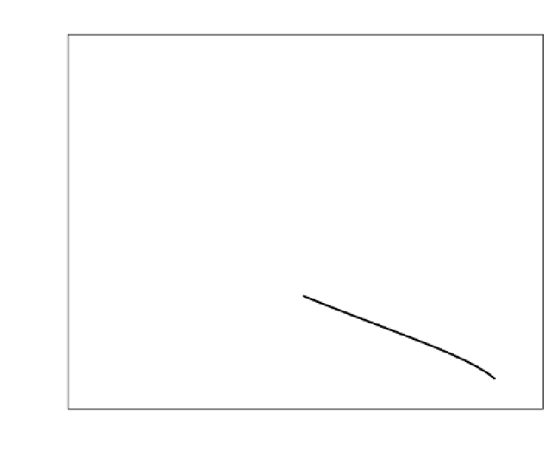
,n) overview
100
(27,34)
(30,38)
(24,30)
(18,22)
(15,18)
90
(9,10)
(21,26)
(12,14)
(6,6)
80
70
60
(21,11)
50
40
(17,9)
30
FIR
(13,7)
IIR
20
(9,5)
N
Op
: Number of operations
n: The filter order
10
(5,3)
0
0.05
0.1
0.15
0.2
0.25
0.3
0.35
0.4
0.45
0.5
2f
p
/f
n
Fig. 10. Expenditure curves of real linear-phase FIR and minimum-phase IIR HBF decimators
based on equiripple minimax designs [Parks & Burrus (1987)]
2.2 Complex Halfband Filters (CHBF)
A complex HBF, a classical Hilbert-Transformer [Lutovac et al. (2001); Mitra & Kaiser (1993);
Schüssler & Steffen (1998; 2001); Schüssler & Weith (1987)], is readily derived from a real HBF
according to Subsection 2.1 by applying the
z
-transform modulation theorem (3) by setting in
compliance with (2)
e
±
j
2
e
j
2
π
f
±
2
/
f
n
z
c
=
z
=
z
=
=
=
±
j
,
(18)
±
∓
2
6
=
±
(Ω
±
2
=
thus shifting the real prototype HBF to a passband centre frequency of
f
f
n
/4
±
2
±π
)
=
/2
. For convenience, subsequently we restrict ourselves to the case
f
c
f
2
.
2.2.1 Linear-Phase (LP) FIR filters
In the FIR CHBF case the frequency shift operation (3) is immediately applied to the impulse
response
h
(
)
in the time domain according to (3). As a result of the modulation of the
impulse response (9) of any real LP HBF on a carrier of frequency
f
2
according to (18), the
complex-valued CHBF impulse response
k
n
2
≤
n
2
e
jk
2
h
k
=
h
(
k
)
−
k
≤
(19)
is obtained. (Underlining indicates complex quantities in time domain.) By directly equating
(19) and relating the result to (9), we get: