Image Processing Reference
In-Depth Information
Phase-shi
f
ter φ(ω)
I-channel
signal
PI(t)
Forward(t)
Low-pass
filter
All-pass
filter
All-pass
filter
H4(z)
All-pass
filter
H6(z)
All-pass
filter
H8
(
z)
Subtraction
H2(z
)
(fc=20kHz)
Phase-shifter φ(ω+α)
Reverse(t)
Q-channel
signal
PQ(t)
Addition
Low-pass
filter
All-pass
filter
All-pass
filter
All-pass
filter
All-pass
filter
(fc=20kHz)
H1(z)
H3(z)
H5(z)
H7(z
)
Phse-shifter φ(ω)
(degree)
Phse-shifter φ(ω+α)
(degree)
H2,H4,H6,H8
(degree)
H1,H3,H5,H7
(degree)
H3
H5
H2
H8
H6
H1
H7
H4
Phse-shifterφ(ω)
Phse-shifterφ(ω+α)
Frequency (Hz)
Frequency (Hz)
Fig. 3. Outline of analog direction separation system
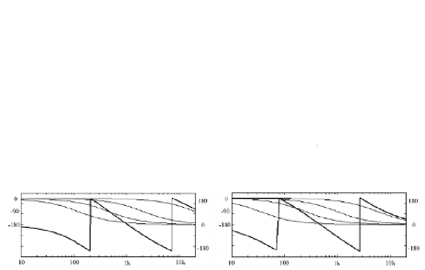
Phase
(degree)
α
PI
QI
Frequency (Hz)
(a) Phase characteristics of
PI
,
PQ
and α
Phase
(degree)
α
Frequency (Hz)
(b) Difference α between
PI
and
PQ
Fig. 4. Frequency characteristics of all-pass filters
In Fig. 4(b), the phase characteristics of I-channel and Q-channel are delayed as frequency
becomes high. Here, the phase characteristics of I-channel and Q-channel are defined to be
()
and
, respectively. The output of I-channel and Q-channel are set to
PI(t)
and
()
PQ(t)
.
PI t
() Re () exp( ( ( )
x t
j
))
sign
(
) sin(
t
( ))
(5)
d
d