Environmental Engineering Reference
In-Depth Information
purposes) we will derive from the small-signal equivalent circuit from an AC
schematic by replacing each transistor with its small-signal model and
evaluating the circuit parameters. Later in the topic, we can briefly refer to
the results obtained below without requiring further investigations.
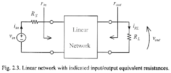
The small-signal equivalent circuit is obtained by linearising the circuit
around its operating point. Figure 2.3 depicts a linear two-port network,
whose output is terminated by a load resistance The output signals,
voltage or current are generated in response to an input port signal
whose equivalent voltage and resistance are respectively,
and
Thus, a
voltage and a current gain can be defined between
and
and
and
Important parameters of this system are the input and output resistances seen
at the input and output ports, which are responsible for a signal loss at the
input and output when coupled with resistances and We will denote
these two resistances with and respectively. The use of lowercase
variables and subscripts is to remind us that these are small-signal
resistances. Note that in general they depend on the load and source
resistances, respectively.
In the rest of the chapter we will analyse the four basic single-transistor
configurations. Since these schemes are covered in many electronic circuit
textbooks, we will assume that the reader is familiar with their complete
analysis (including biasing techniques, AC coupling, etc). Here we will
recall only their salient small-signal features.