Environmental Engineering Reference
In-Depth Information
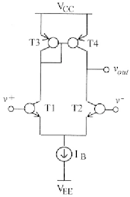
The circuit exhibits a local feedback (through the current mirror T3-T4)
which must be taken into account to accurately evaluate its output resistance
To this end, we present the simplified AC diagram in Fig. 9.2, where the
current mirror is modelled with a unitary controlled current source,
i
and its
associated output resistance, equal to the output resistance of transistor
T4 (the mirror input resistance, approximately equal to has been
neglected as it is connected in series to the high-impedance Z terminal of
transistor T1). Finally,
resistor
models the output resistance of the current
source
The output resistance is due to the parallel combination of the up and
down contributions,
where is exactly the same as the output resistance seen at terminal Z of
transistor T4,