Environmental Engineering Reference
In-Depth Information
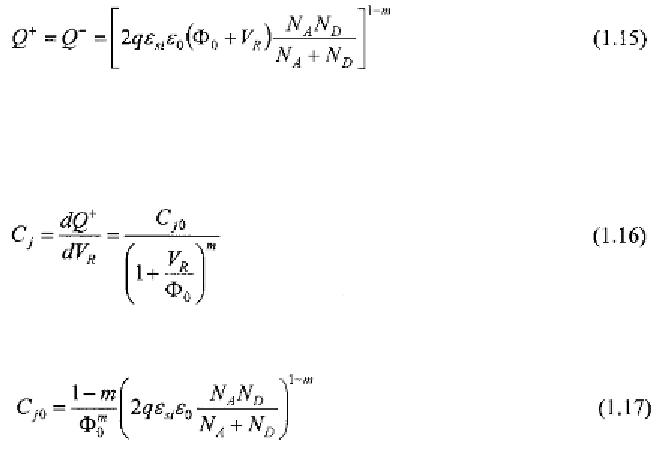
from p to n, a better model for the charge can be described by changing the
exponent in (1.12) as follows [4]
where
m
is a technology dependent parameter (typical
m
values are around
1/3).
In this case, the junction capacitance per unit of area turns into
where
1.2.3
Forward Bias Condition
With reference to Fig. 1.3, by grounding the cathode and applying a
voltage to the anode, we forward-bias the device. Under this condition
the built-in potential is reduced by the amount of voltage applied.
Consequently, the width of the depletion region and the charge stored in the
junction are reduced, too.
If is large enough, the reduction in the potential barrier ensures the
electrons in the n side and the holes in the p side are attracted by the anode
and the cathode, respectively, thus crossing the junction. Once free charges
cross the depletion region, they become minority carriers on the other side
and a recombination process with majority carriers begins. This
recombination reduces the minority carrier concentrations that assume a
decreasing exponential profile. The concentration profile is responsible for
the current flow near the junction, which is due to a diffusive phenomenon
that is called diffusion current. On moving away from the junction, some
current flow is given by the diffusion current and some is due to majority
carriers that, coming from the terminals, replace those carriers recombined
with minority carriers or diffused across the junction. This latter current is
termed a drift current.