Environmental Engineering Reference
In-Depth Information
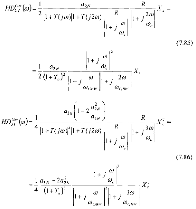
This scheme is equivalent to the one analysed in Fig. 7.8 by properly
updating the block transfer functions. Hence, utilising (7.55) and (7.56) we
get
Both the above distortion factors increase for frequencies higher than the
amplifier pole. As a consequence, their effects can be significant at high
frequencies.
To qualitatively compare the effects on output distortion due to the output
resistance and the input transconductance, let us consider the plots in Fig.
7.16. They illustrate the typical behaviour of second harmonic distortion
factors due to the nonlinear output resistance,
and due to the input
transconductance,
The frequency determining which contribution is