Environmental Engineering Reference
In-Depth Information
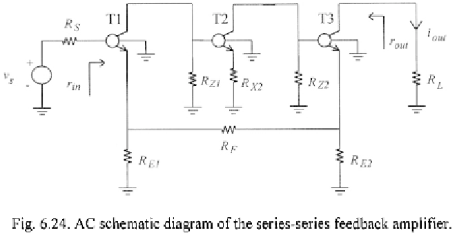
From a comparison of series-series feedback circuit in Fig. 6.24 with
series-shunt feedback amplifier with output buffer in Fig. 6.9, it is apparent
that the only difference between the two amplifiers is the load resistance at
node Z of transistor T3. Therefore, unless some minor differences we can
follow the same analysis we have previously developed for the series-shunt
amplifier with output buffer. In particular choose as controlled source
P
the
transconductance
and proceed with the following steps.
1)
Set Assuming transistor T1 implementing an ideal
voltage buffer and transistor T3 implementing an ideal current buffer, the
feedforward transconductance can be directly derived by inspection of Fig.
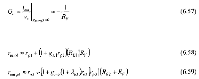
6.24, and results to be
Moreover, the open-loop input and output resistances are about equal to
2)
Replace the controlled current generator with an independent current
source,
i
, and set the input voltage source to zero. In this case, neglecting the
effect of load resistance on the accuracy of the voltage follower implemented