Environmental Engineering Reference
In-Depth Information
node of the controlled source is at ground potential. This means that for
multi-transistor amplifiers we can profitably choose the controlled source
among those associated to a common X transistor. According to this
heuristic rule, in the small-signal model of the series-shunt amplifier we
choose as controlled source
P
the transconductance and apply the
Rosenstark method as described in the steps below. Observe that whenever
possible we prefer evaluating the circuit parameters directly on the AC
schematic. In our opinion, this is essential to develop the indispensable skills
required to an analog circuit designer.
1)
To evaluate the direct transmission term, we set
This, unless a load effect on terminal Z of T1, means eliminating transistor
T2 and leading to the AC schematic diagram depicted in Fig. 6.3. It clearly
represents a voltage follower whose transfer gain was derived in paragraph
2.6 and is expressed by relationships (2.28a) and (2.29). Then, substituting
and to and respectively, and including term
which takes into account the voltage partition at the output of
the voltage buffer (resistance
has been considered much higher than
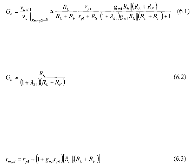
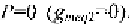
we get the gain,
under the special condition of zero feedback
Resistance is the resistance seen at the Yl terminal of circuit in Fig. 6.3.
In common cases, where and the intrinsic voltage gain of the
common Z configuration is close to the unity, relationship (6.1) can be
further simplified into
which shows that this contribution is always lower than one. Thus, the direct
transmission term, can be neglected without introducing appreciable
errors in the evaluation of the closed-loop gain.
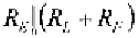
Under the same condition of controlled source set to zero, we can
evaluate the driving point input and output resistances,
and
by
using (2.24) and (2.25),
respectively. We rearrange below the simplified
expressions of
and
by considering