Environmental Engineering Reference
In-Depth Information
Equation (5.49) allows an interesting interpretation of the compensation
process. We will show that assuming a dominant-pole frequency response,
the second and third stage can be considered as closed in a unity-gain
feedback configuration by capacitor
acting as a short circuit for
frequencies above
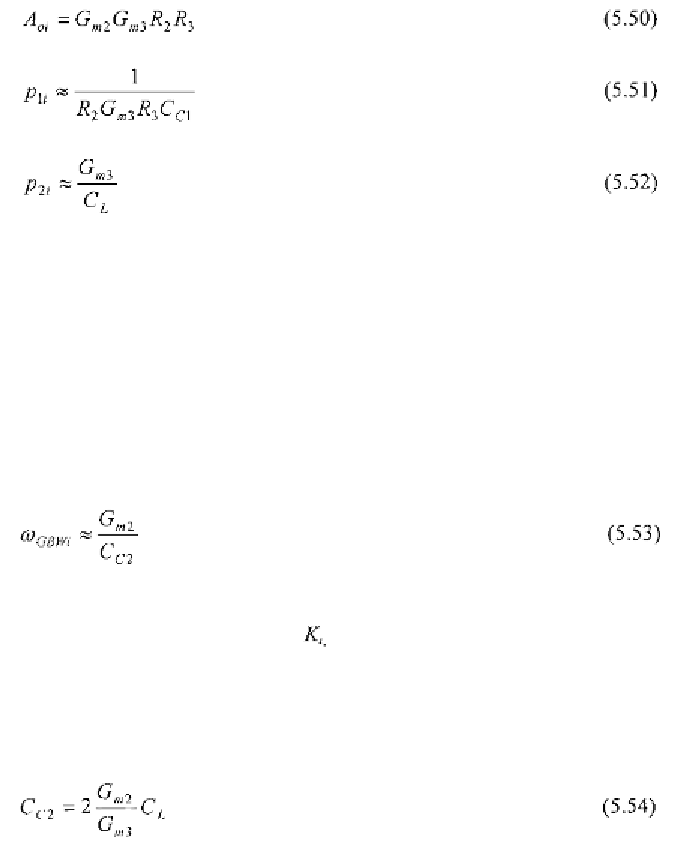
Consider now the open-loop gain of the second and third stage alone
(which we also refer to as the
inner
amplifier),
its DC gain, the
dominant
pole
dueto the Miller effect on
and the second pole
at
the output terminal. They are given by
If now we assume in unity-gain feedback connection, the resulting
closed-loop transfer function is characterised by exactly the same second-
order polynomial as in the denominator of (5.49). This consideration justifies
the representation utilised in equation (4.54) and allows, in turn, the
straightforward compensation technique discussed below.
For a well designed (i.e., with appropriate stability margins) inner
amplifier, the second pole
must be located well beyond the unity-gain
frequency
which,
under
the
dominant-pole
behaviour
assumption, is
approximately equal to
and given by
In order to avoid overshoot in the module of the inner amplifier
frequency response, a proper ratio, between and has to be set as
described in paragraph 4.5. A fairly optimum value of is 2 (i.e. an inner
phase margin of about 64°) which is the minimum value guaranteeing
monotonic behaviour in the frequency response module. This leads to the
expression of capacitor