Environmental Engineering Reference
In-Depth Information
impact of on the compensated frequency response inconsequential. But
for MOS and CMOS technologies, the transconductance is small, and as a
result, the effects of the RHP zero evidenced in the forward transfer function
of a phase inverting amplifier may not be negligible. When the transmission
zero is significant, its primary effect is to incur excess phase lag (phase lag
in addition to that produced by the two open-loop poles), while prohibiting a
uniform 20 dB-per-decade frequency response roll-off rate at high
frequencies. The stability problems caused by the resultant deterioration in
phase margin justifies the implementation of compensation techniques that
neutralise the effects of the RHP zero.
Various compensation schemes have been proposed for two-stage MOS
opamps. They are based on the concept of breaking the forward path through
the compensation capacitor by using active or passive components. The first
of these was applied in a NMOS opamp [TG76] and then in a CMOS opamp
[SHG78]. It breaks the forward path by introducing a voltage buffer in the
compensation branch. Next, a compensation technique was proposed which
uses a nulling resistor in series with the compensation capacitor [A83].
Another solution works like the former but uses a current buffer to break the
forward path [A83]. Finally, both current and voltage buffers can be adopted
to compensate the right half-plane zero
[MT90].
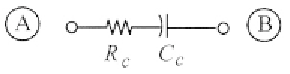
5.3.1 Nulling Resistor
The most widely used compensation technique is the one based on the
nulling resistor. It entails the incorporation of a resistor,
in series with
the Miller compensation capacitor as shown in Fig. 5.3.
The popularity of this scheme stems from the fact that it can be
implemented monolithically with a MOS transistor biased in its triode
regime (which approximates a linear resistor). Moreover, its highpass nature
does not reduce the low-frequency dynamic range of the imcompensated
configuration. By using this compensation branch in the equivalent circuit in
Fig. 5.2, and neglecting capacitance
(usually much lower than
), the
zero is now at frequency