Geoscience Reference
In-Depth Information
|
1/2
u
*
=|
τ
H
f
=
ρ
c
p
<w
T
>
0
0
Model
TICs
u
*0
-
5
-
5
-
10
-
10
Model
TICs
H
f0
-
15
-
15
-
20
-
20
-
25
-
25
30
-
30
-
-
35
-
35
a
b
-
40
-
40
0
0.005
0.01
0.015
0.02
0
10
20
m s
-
1
W m
-
2
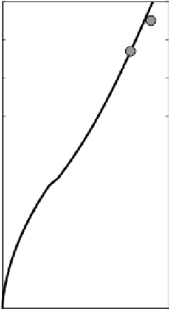
Fig. 9.5 a
Friction velocity (square root of kinematic Reynolds stress) as modeled (solid) and
measured at two levels. The surface value (square) symbol was chosen so that the modeled value
at 6mmatched measured.
b
. Corresponding profiles and measurements of turbulent heat flux. The
interface value(square) iscalculated from
u
∗
0
,
T
and
S
in theupper ocean
6m belowthe interface.Butin a well developed,turbulentboundarylayer,the 6-m
current comprises contributions from stress-driven shear in OBL, any inertial mo-
tioninthephase-lockedice/upperoceansystem,plusthegeostrophiccurrentarising
from slope in the sea surface. The last is the current that would exist without any
shearbetweentheice andundisturbedocean.
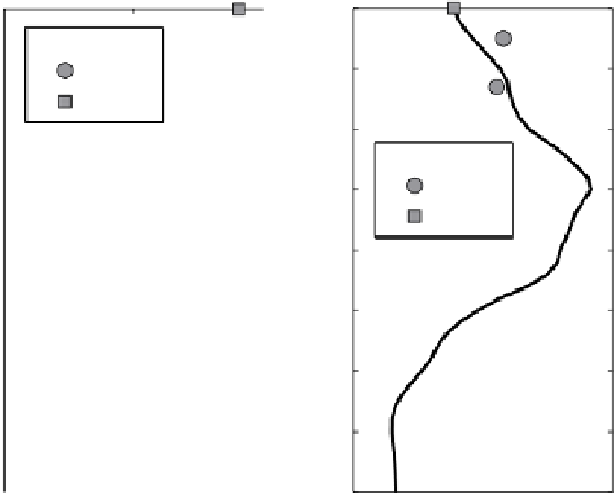
Since there is no provision in the SLTC model for inertial oscillations and in
general the vector sum of geostrophic and inertial velocities at the measurement
level is unknown, the surface roughness may be estimated from current measure-
mentataparticularlevelasdiagrammedinFig.9.6.Thepremiseisthatthetopmost
pointin the meanquantity(
zz
) gridis within the surface layer so that surfacestress
and shear are aligned, in which case the velocity difference between the topmost
gridpointandtheiceobeysthelawofthewall:
κ ∆
u
u
∗
0
=
ln
|
zz
1
|
z
0
(9.2)
Geometrically,
∆
u
is determined by the intersection of an arc with length equal
to the magnitude of the measured current (indicated by
V
m
(
rel
)
)
, swung from the
tip of the absolute model velocity vector
at the measurement depth, and
a line extended in the direction of
u
∗
0
from the velocity at the topmost grid point.
(
V
m
(
abs
)
)