Geology Reference
In-Depth Information
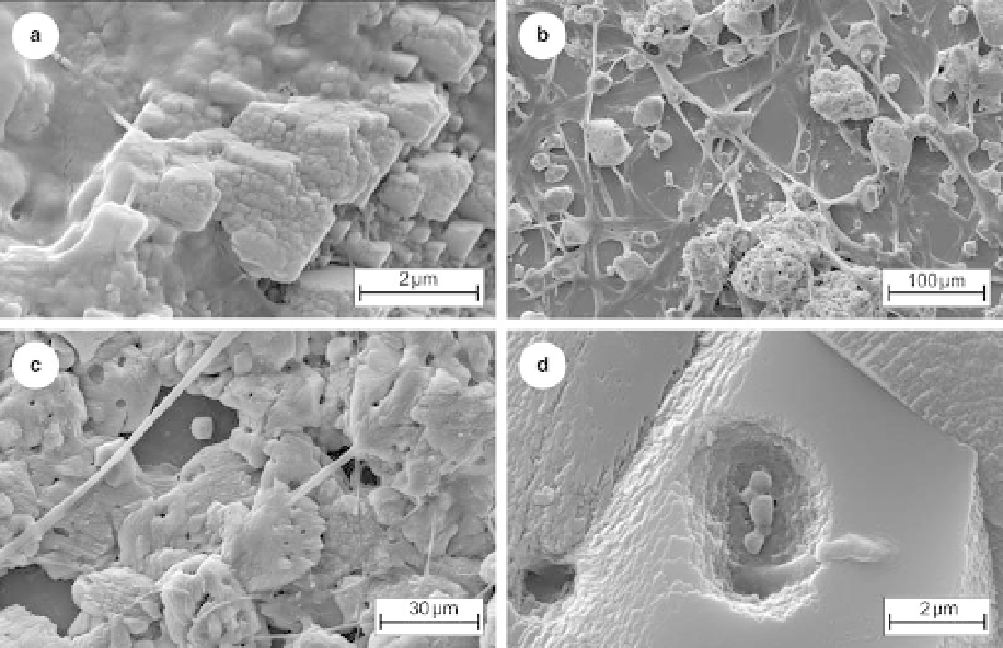
Fig. 3. (a) Initial development of crystal faces on a nanospherulite aggregate, all intimately associated with EPS
(smooth areas especially on the left). Note the apparently random stacking of nanospherulites. Nevertheless, incipient
rhombic face development can also be seen. Autumn, fast-flow experiment, SEM view. (b) Initiation of calcite
precipitation within the biofilm (glass slide substrate). Micropeloids, composed of nanospherulites and well formed
calcite rhombs are visible, all linked by dehydrated strands of EPS. Summer, slow-flow experiment, air dried SEM
sample after 28 days. (c) Details of the early calcite precipitates showing the ubiquitous development of irregular to
elliptical cavities within the embryonic calcite crystals. During continued crystal growth these EPS areas are
progressively occluded by further calcite precipitation, both internally and also on to the outer surface of the crystals.
SEM view. (d) Cavities within a microspar crystal. The central surface depression was originally occupied by EPS (now
dehydrated) and coccoid heterotrophic bacteria. The deeper cavity to the left was occupied by a strand of EPS. Autumn,
slow-flow experiment. Air dried SEM sample.
Typically, this layer developed into an interlocking
crystalline calcite fabric which frequently was seen
to be physically attached to the substrate (Fig. 4b).
Nevertheless, abundant EPS strands and living
microbial attachments continued to extend through
the crystals and around them imparting a micro-
cavernous fabric to the basal calcite layer (Fig. 4).
Other calcite precipitates also developed,
apparently randomly, within the thin EPS sheet
and above the basal calcite layer in the summer
biofilm. In the thicker autumn biofilm, however,
these precipitates were focused within the EPS
into narrow polygonal zones (Fig. 5a) associated
with high concentrations of heterotrophic bacteria
(Fig. 5b). Individual micropeloids and anhedral
microspar within these narrow polygonal zones
were largest and most densely packed close to the
basal calcite layer (see Fig. 5c) where the precipi-
tates had intergrown to form vertical septae. At
their base, these septae also appeared to intergrow
with other microspar crystals precipitated within
the base of the EPS layer directly above the basal
calcite layer (Figs 4a & 5a).
Calcite precipitates in the aphotic (sump) EPS
A well formed rhombic calcite mosaic also devel-
oped ubiquitously in all submerged sump areas
from the air water interface down to the sump
bottom and also on the surface of the pump
(Fig. 6a). This distribution of precipitates argues
against precipitation solely via degassing of CO
2
,
which tends to occur at the air-water interface
(Rogerson et al. 2008). The tightly interlocking
calcite crystals were pale brown in colour (cf. pale
grey precipitates in the photic zone) and were com-
monly buried in EPS (Fig. 6b). Typically, crystals
were pockmarked with cavities and 1-5 mm holes
in the same characteristic manner as seen in bio-
mediated precipitates developed within photic
Search WWH ::

Custom Search