Environmental Engineering Reference
In-Depth Information
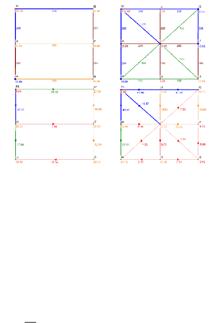
Figure 5.12
Adapted net10 and net16 - pipes: D (mm), Q (l/s), nodes: Q (l/s), p/ρg (mwc)
In order to describe the network resilience, Todini (2000) uses the concept of power balance
between (1) the sources of supply, (2) the dissipated amount due to the network hydraulic
losses, and (3) the remainder at discharge points. It is valid in all situations that:
l
k
n
m
t
∑
∑
∑
∑
∑
Q
H
+
Q
h
=
Q
H
+
Q
h
+
Q
h
5.19
s
s
p
p
i
i
j
f
,
j
v
m
.
v
s
=
1
p
=
1
i
=
1
j
=
1
v
=
1
H
s/i
in Equation 5.19 indicate the piezometric heads at
l
sources (which includes all the
reservoirs, and tanks that supply the network), and
n
nodes (which includes all the junctions
with discharge, and tanks that are supplied from the network), respectively. The values of
h
p/f/m
include the heads of
k
pumps, the pipe friction losses of
m
pipes and the minor losses of
t
major valves. In all cases,
Q
s/p/i/j/v
stand for corresponding flows supplying the network (
s
),
being conveyed through it (
p,j
and
v
), or withdrawn from it (
i
). Todini's resilience index,
I
r
, is
a measurement of the system's vulnerability of letting some nodes without service in the
occurrence of failure, expressed as:
*
int
P
I
r
=
1
−
5.20
*
max
P
P
*
int
in Equation 5.20 is the amount of power dissipated in the network to satisfy the total
demand,
Σ Q
i
, under regular operation i.e. at the minimum required pressure, and
P
*
max
is the
maximum power that would be dissipated internally during the pipe failure in order to satisfy
the constraints of the demand and pressure in the nodes. By substituting Equation 5.19 into
5.20, the
I
r
can be expressed as:
Search WWH ::

Custom Search