Environmental Engineering Reference
In-Depth Information
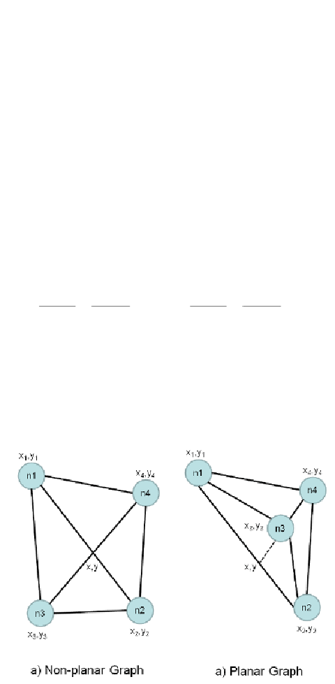
Fraysseix, et al. (2006). The assessment of planarity applied in this study uses spatial
coordinates to find possible intersection point. The intersection point (
x
,
y
) of two edges that
are connecting the vertices (
x
1
,
y
1
) and (
x
2
,
y
2
), and vertices (
x
3
,
y
3
) and (
x
4
,
y
4
), respectively,
is given by the following equations:
1
(
)
4.1
x
=
y
−
y
−
m
x
+
m
x
;
y
=
m
x
−
m
x
+
y
3
1
2
3
1
1
1
1
1
1
m
−
m
1
2
where m
1
and m
2
are slopes of the edges that are calculated as:
y
−
y
y
−
y
4.2
m
=
2
1
;
m
=
4
3
1
2
x
−
x
x
−
x
2
1
4
3
If the two edges intersect, they are divided by the intersection point (
x
,
y
) in the proportions
k
1
and
k
2
in the following way:
x
−
x
y
−
y
x
−
x
y
−
y
4.3
k
=
1
=
1
;
k
=
3
=
3
1
2
x
−
x
y
−
y
x
−
x
y
−
y
2
2
4
4
Positive values of
k
indicate that the intersection point cuts the edge internally while the
negative values indicate external cuts, meaning that the intersection point is outside the edge.
Both situations are illustrated in Figure 4.9, left and right, respectively. Thus, the condition
for two edges not to be intersected is that the
k
-value should be negative for both edges.
Figure 4.9
Intersection point in non-planar graph
4.4
GENERATION PROCESS
A set of generated networks is in fact a set of planar sub-graphs connecting all available
vertices. Eliminating any discovered crossing of edges will actually lead to two alternative
planar layouts, as has been shown in Figure 4.8 and Table 4.7.


Search WWH ::

Custom Search