Image Processing Reference
In-Depth Information
Z
X
O
Y
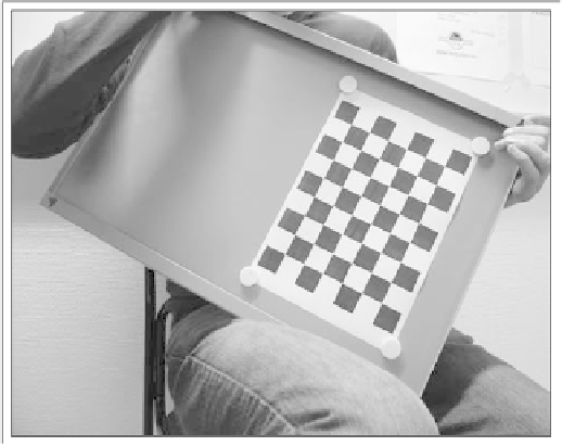
Fig. 13.5. A camera to be calibrated takes the picture of a known pattern
⎛
⎞
M
31
M
32
M
33
⎝
⎠
=
c
0
(
M
11
,M
12
,M
13
)
⎛
⎞
M
31
M
32
M
33
⎝
⎠
=
r
0
.
(
M
11
,M
12
,M
13
)
M
11
+
M
12
+
M
13
=
f
x
+
c
x
.M
21
+
M
22
+
M
23
=
f
y
+
c
y
.
where the observation that different rows of
R
are orthogonal has been utilized. In the
equations,
M
ij
are the known parameters, to the effect that the intrinsic parameters
can be pulled out without effort. Once the intrinsic parameters are known, they can
be substituted into Eq. (13.63) so that
t
is identified from the last column, whereas
R
is identified from the remaining columns, i.e., the first 3
×
3 block matrix on the
left.
Using the above procedure, from every
M
, one can estimate
M
I
,
M
E
. However,
for every registered view of the calibration pattern, one can obtain an
M
and thereby
a pair of
M
I
,M
E
. A series of views containing the pattern can thus be shot by mov-
ing and/or tilting it randomly, yielding a sequence of matrices
M
I
and
M
E
, where
M
I
is the estimate of a constant matrix, the intrinsic parameters. The intrinsic pa-
rameters of the camera should remain unchanged so that an average of the matrices
M
I
will be a better estimate of the intrinsic matrix as compared to that of an indi-
vidual calibration. The matrix
M
E
will nevertheless be different for each calibration
because each estimated
M
E
encodes the rotation and the distance of the calibra-